2. Wiring
Fieldbus Communication
46
RCP6
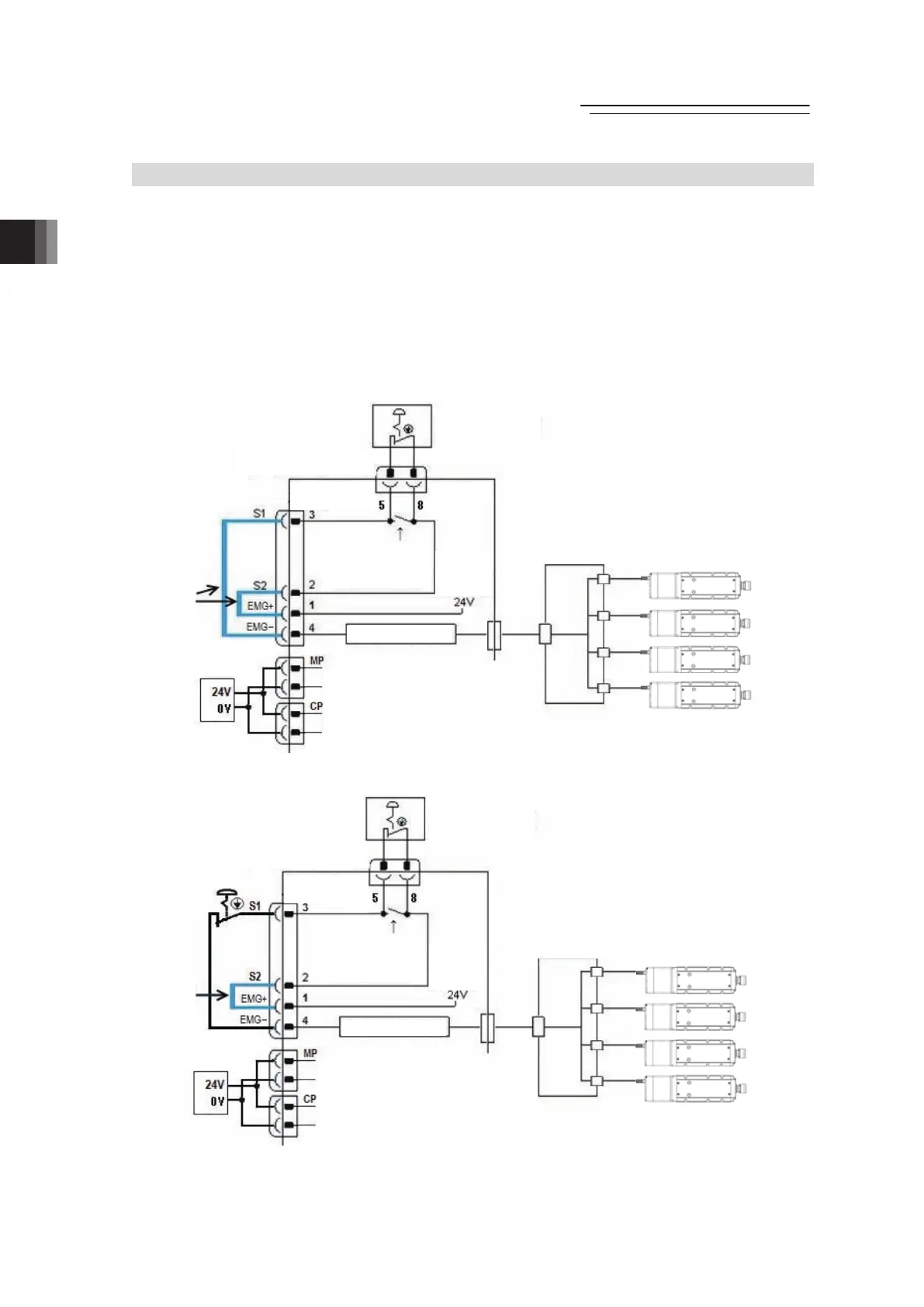
2.2 Circuit Diagram
[1] Power Supply and Emergency Stop
As an example of a circuit, cases of 4 conditions are shown.
Select from 3) or 4) for RCM-P6GWG type.
1) Wiring to drive an actuator using only emergency stop input from a teaching tool.
2) Wiring to drive an actuator by activating devices and emergency stop input (EMG-) from a
teaching tool.
3) Stop supplying external motor power at emergency stop input.
4) Shut off the motor power externally by inputting the emergency stop with using two units of
controllers or more.
1) Example of wiring to drive an actuator using only emergency stop input from a teaching tool
2) Example of wiring to drive an actuator by activating devices and emergency stop input (EMG-)
from a teaching tool
RCP6S Actuator or
RCP6S Gateway Controllers
Built in Drive Cutoff Circuit
(MAX.16 units)
Teaching Tool
Operation
Stop Switch
System I/O
Connector
SIO
Connector
Teaching
Tool Connection
Detection Circuit
(Contact opens
when connected)
Dedicated
Operation
Stop
Circuit
Wiring
Conducted
at Delivery
Operation Stop
Detection Times
Hub Unit
Gateway Unit
24V DC
Power Supply
Motor Power Supply
Control Power Supply

 Loading...