3. Operation
Fieldbus Communication
118
RCP6
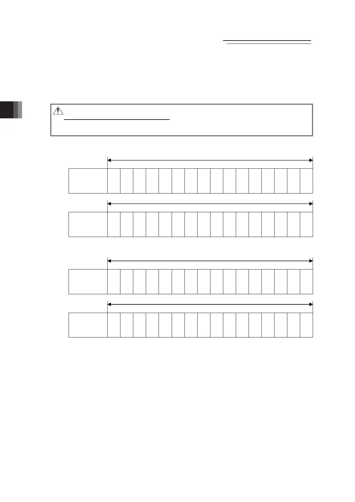
(2) Input and Output Signal Assignment for each Axis
The I/O signals for each axis consists of 2-word for each I/O bit register.
● The control signals and status signals are ON/OFF signals in units of bit.
● For the indicated position number and complete position number, 1-word (16-bit) binary data
is available and values from 0 to 767 can be used.
Caution:
Set the operational condition in advance
with using a teaching tool such as PC software in the
position number to be used. Selecting a position number with no setting conducted will
generate the alarm code 0A2 “Position Data Error”.
PLC Output (m is PLC output top word address for each axis number)
Address m
b15 b14 b13 b12 b11 b10
b9 b8 b7 b6 b5 b4 b3 b2 b1 b0
Specified
Position No.
–
–
–
–
–
–
PC512
PC256
PC128
PC64
PC32
PC16
PC8
PC4
PC2
PC1
Address m+1
b15 b14 b13 b12 b11 b10
b9 b8 b7 b6 b5 b4 b3 b2 b1 b0
Control Signal
BKRL
–
–
–
–
MODE
PWRT
JOG+
JOG-
JVEL
JISL
SON
RES
STP
HOME
CSTR
PLC Input (m is PLC input top word address for each axis number)
Address m
b15 b14 b13 b12 b11 b10
b9 b8 b7 b6 b5 b4 b3 b2 b1 b0
Completed
Position No.
–
–
–
–
–
–
PC512
PC256
PM128
PM64
PM32
PM16
PM8
PM4
PM2
PM1
Address m+1
b15 b14 b13 b12 b11 b10
b9 b8 b7 b6 b5 b4 b3 b2 b1 b0
Status Signal
EMGS
CRDY
ZONE2
ZONE1
PZONE
MODES
WEND
MEND
ALML
LOAD
PSFL
SV
ALM
MOVE
HEND
PEND
1 word = 16 bit
1 word = 16 bit
3.4.6

 Loading...