Server controls, LEDs, and power
This section describes the controls and light-emitting diodes (LEDs) and how to
turn the server on and off.
For the locations of other LEDs on the system board, see “System-board LEDs” on
page 29.
Front view
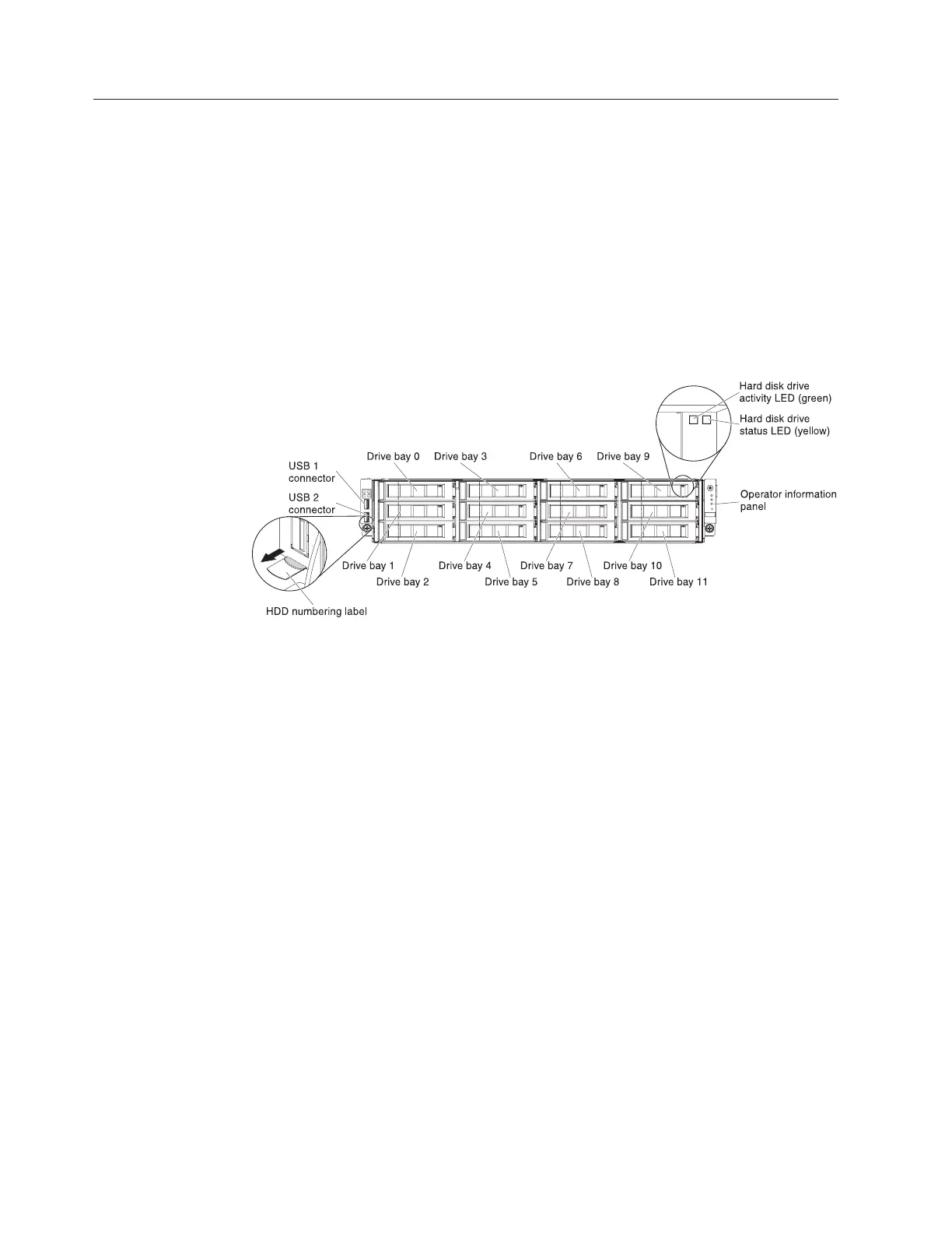
The following illustration shows the controls, connectors, and hard disk drive bays
on the front of the server.
12 hot-swap hard-disk drive configuration:
v USB connectors: Connect a USB device, such as USB mouse or keyboard to
either of these connectors.
v Hard disk drive activity LEDs (green):This green LED is used on hot-swap SAS
or SATA hard disk drives. Each hot-swap hard disk drive has an activity LED,
and when this LED is flashing, it indicates that the drive is in use.
v Hard disk drive status LEDs (yellow):This yellow LED is used on hot-swap
SAS/SATA hard disk drives. Each hot-swap hard disk drive has a status LED.
When this LED is lit, it indicates that the drive has failed. When this LED is
flashing slowly (one flash per second), it indicates that the drive is being rebuilt
as part of a RAID configuration. When the LED is flashing rapidly (three flashes
per second), it indicates that the controller is identifying the drive.
v Operator information panel: This panel contains the power control button and
light-emitting diodes (LEDs).
Figure 4. 12 hot-swap hard-disk drive configuration
16 System x3650 M4 BD Type 5466: Installation and Service Guide

 Loading...


