Table 3. System board jumpers (continued)
Jumper number Jumper name Jumper setting
Note:
1. If no jumper is present, the server responds as if the pins are set to 1 and 2.
2. Changing the position of the UEFI recovery jumper from pins 1 and 2 to pins 2 and 3
before the server is turned on sets the UEFI recovery process. Do not change the
jumper pin position after the server is turned on. This can cause an unpredictable
problem.
Important:
1. Before you change any switch settings or move any jumpers, turn off the
server; then, disconnect all power cords and external cables. (Review the
information on page“Safety” on page vii, “Installation guidelines” on page 32,
“Handling static-sensitive devices” on page 34, and “Turning off the server” on
page 22.
2. Any system-board switch or jumper blocks that are not shown in the
illustrations in this document are reserved.
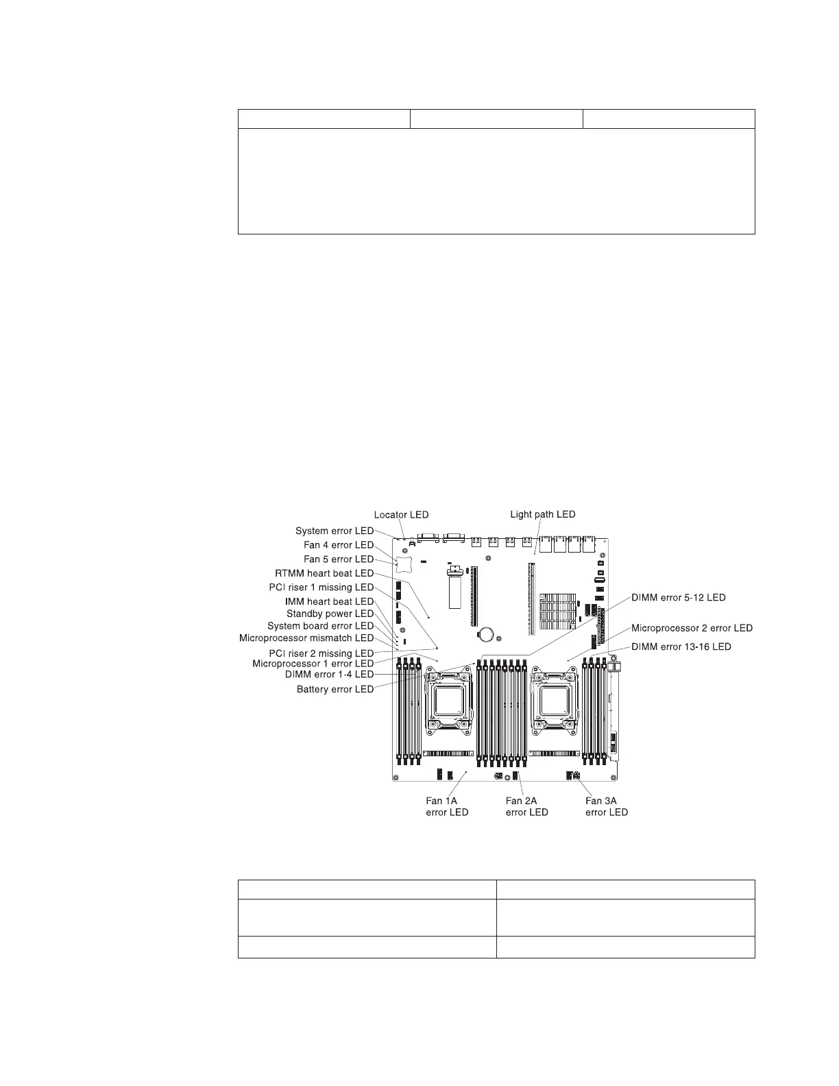
System-board LEDs
The following illustration shows the light-emitting diodes (LEDs) on the system
board.
Table 4. System board LEDs definition
LED name Description
Error LEDs When an error LED is lit, it indicates that
the associated component has failed.
RTMM heartbeat LED Power-on and power-off sequencing.
Figure 15. System board LEDs
Chapter 2. Installing optional devices 29

 Loading...


