2. Pull straight back on the tape drive handle while the bottom of the drive is supported to remove it from
the module.
Attention: Support the bottom of the tape drive when it is removed to avoid damaging any of the
internal connections.
Removing the power supplies
While the power supplies are removed, be sure to support the bottom. For detailed instructions, see
“Adding, removing, or replacing a power supply” on page 160.
Removing the Base or Expansion controller card
For detailed instructions, see “Replacing a Base or Expansion controller card” on page 162.
Removing the Module from a rack
Obtain assistance to lift and stabilize the module during removal and replacement.
• If you are removing a module that has a module immediately above or below it,
1. From the front of the library, use a #2 Phillips screwdriver to loosen the screws two full turns on the
module and its adjacent modules.
2. From the back of the library, unlock the alignment mechanisms that connect the module with the
adjacent modules.
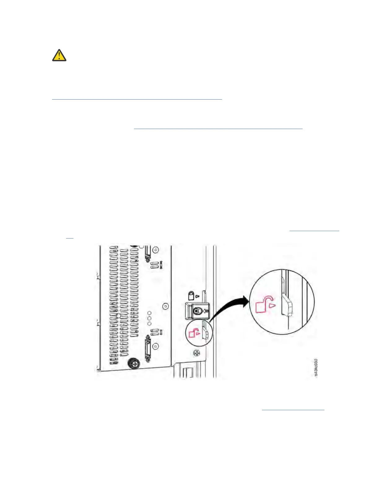
Note: If a blue alignment lever lock is attached to the rear of the module, slide it to the left, then
move the alignment lever. The lever lock has an internal spring, so hold it while the alignment lever is
moved, and it automatically springs back into place after the lever is moved. See Figure 44 on page
61.
Figure 72. Unlocking or disengaging the alignment lever
From the front of the library, use a #2 Phillips screwdriver and your ngers to loosen the captive
thumbscrews screws two full turns on the module to be removed (circled in Figure 73 on page 158).
Then, slide the module out of the rack.
IBM Condential
Chapter 6. Upgrading and servicing157