5
2
PANEL DESCRIPTION
1
2
3
4
5
6
7
8
9
10
11
12
13
14
15
16
17
18
19
!0 EXTERNAL DC IN JACK [DC IN]
± Connects the supplied wall charger, BC-167ND, to
charge the attached battery pack. (p. 12)
± Connect an external DC power supply through the op-
tional CP-12L, CP-19R or OPC-254L for external DC
operation. (p. 15)
!1 DATA JACK [DATA] (pgs. 74, 77, 157)
Connects a PC through the optional data communication
cable, OPC-1529R, for low-speed data communication in
the DV mode or cloning operation. The jack and cable are
also used to connect a GPS receiver.
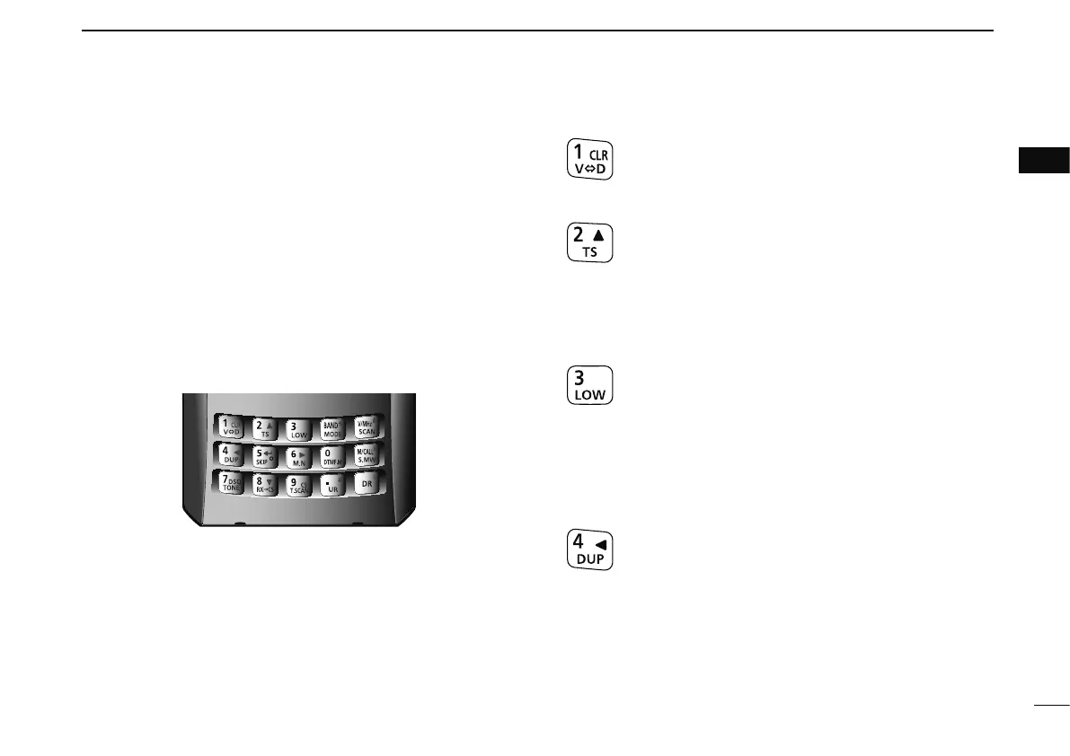
D KEYPAD
± Push to input numeral for frequency input, memory chan-
nel selection, etc.
±
Push to enter or send the DTMF code. (pgs. 143–145)
1 • VOLUME/DIAL KEY [1] • [V
<
=
>
D](1)
± Numeral input and DTMF code: ‘1’
±
Push and hold for 1 sec. to exchange the assigned
functions between [DIAL] and []/[]. (p. 20)
2 • TUNING STEP KEY [2] • [TS](2)
± Numeral input and DTMF code: ‘2’
± Push and hold for 1 sec. to enter tuning step set
mode. (p. 22)
± During menu screen operation or select memory
write mode, push to select the set items or values.
(p. 115)
3 • OUTPUT POWER KEY [3] • [LOW](3)
± Numeral input and DTMF code: ‘3’
± Push and hold for 1 sec. to select the output
power. (p. 27)
• Selects the transmit output power from high, mid, low
and S-low.
• While pushing and holding this key, [DIAL] rotation se-
lects the output power.
4 • DUPLEX KEY [4] • [DUP](4)
± Numeral input and DTMF code: ‘4’
± Push and hold for 1 sec. to select minus duplex,
plus duplex, and simplex operation. (p. 32)
• “DUP–” (minus duplex), “DUP” (plus duplex) and no
indication (simplex) appear in order.
• While pushing and holding this key, [DIAL] rotation se-
lects the duplex operation.
± During menu screen operation, push to select the
upper layer. (p. 115)