IDEC SmartRelay installation and wiring
IDEC SmartRelay Manual 34
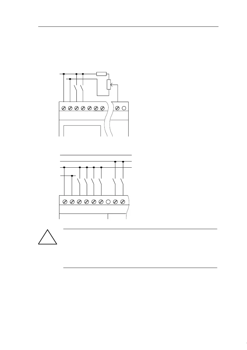
Sensor connections
To connect sensors to the IDEC SmartRelay :
FL1D-H12RCA / FL1D-B12RCA / FL1D-H12RCE / FL1D-B12RCE /
FL1D-H12SND
FL1D-H12RCC / FL1D-B12RCC
!
Warning
Current safety regulations (VDE 0110, ... and IEC 61131-2, ... as
well as cULus) do not permit the connection of different phases to
an AC input group (I1 to I4 or I5 to I8) or to the inputs of a digital
module.
L+ *)
M
ML+ I1 I2 I3 I4 I5 I8
The inputs of these devices are not
isolated and therefore require a
common reference potential (chassis
ground ).
With FL1D-H12RCE/FL1D-B12RCE
and FL1D-H12SND modules, you can
tap analog signals between the
supply voltage and chassis ground
(* = series resistor with 24 V DC).
L1
N
L3
L2
NL1 I1 I2 I3 I4 I5 I6
The inputs of these devices are
arranged in 2 groups, each consisting
of 4 inputs. Different phases are only
possible between blocks, but not
within the blocks.
Courtesy of Steven Engineering, Inc. ● 230 Ryan Way, South San Francisco, CA 94080-6370 ● General Inquiries: (800) 670-4183 ● www.stevenengineering.com
 Loading...