IDEC SmartRelay installation and wiring
35
IDEC SmartRelay Manual
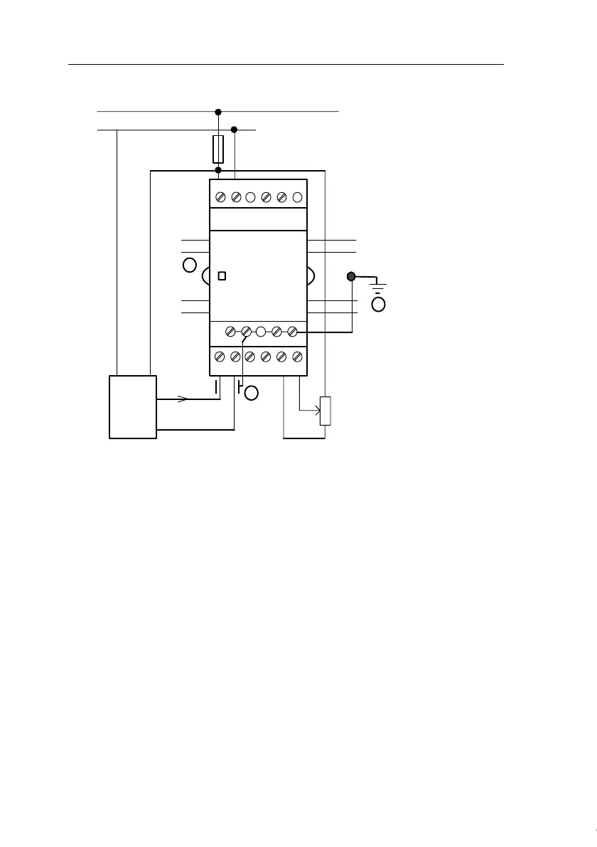
FL1B-J2B2
The illustration above shows an example of four-wire current
measurement and two-wire voltage measurement.
Connecting a two-wire sensor to the FL1B-J2B2
Wire up the two-wire sensor's connecting wires as follows:
1. Connect the sensor's output to connection U (0 ... 10 V
voltage measurement) or to connection I (0 ... 20 mA cur-
rent measurement) of the FL1B-J2B2 module.
2. Connect the plus connector on the sensor to the 24 V
supply voltage (L+).
Connect the ground connection on the sensor to the corre-
sponding M input (M1 or M2) on the FL1B-J2B2 module.
ML+
L
M
U1 I2 M2 U2I1 M1
PE
L
+
M
1
2
3
RUN/STOP
M
ML+
PE
PE terminal for
connecting earth and
the shielding of the
analog measuring
cable
1 Earth
2 Cable shielding
3 DIN rail
Reference
current
Current
0...20mA
Current measurement
Voltage measurement
Courtesy of Steven Engineering, Inc. ● 230 Ryan Way, South San Francisco, CA 94080-6370 ● General Inquiries: (800) 670-4183 ● www.stevenengineering.com
 Loading...