HANDLING AND INSTALLATION
4
302.028
- 23 -
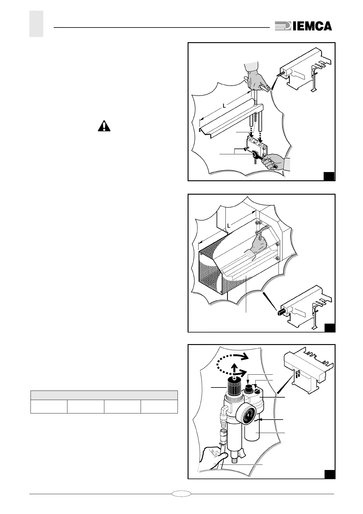
4.5.5 Bar passage guide - Installation
(fig. 18)
– Saw the guide of the length
L
necessary to cover
the distance between bar feeder and lathe spindle.
– Position it in its seat.
– Adjust the guide height. The bar axis (resting on the
bar) should be aligned with the feeding axis.
– To adjust, turn screw
A
.
– Tighten the nuts
B.
DANGER - WARNING: it is critical to install the
protection guard to guarantee safety.
– Cut the guard
D
(fig. 19) to a length
L
necessary to
cover the distance between the feeder and the
lathe.
– Fix the guard with screws.
4.6. PNEUMATIC CONNECTION
– Unscrew plug
B
or cup
C
to fill the tank of lubricator
A
(fig. 20); the oil level shall reach the
MAX
. refe-
rence.
Oil properties: 9 to 11 cSt at 40°C ISO VG 10.
– Connect pipe
D
of the compressed air ductwork
system as shown in the figure. Adjust pressure at 6
bar
by means
of knob
E
.
– Check the air lubrication (1-12 drops per 1000 l air);
adjust through screw
F
.
LUBE OIL TABLE
BP ENERGOL
HP10
SHELL
TELLUS C10
MOBIL
DTE 21
ESSO
SPINESSO 10
20
22.080 Ec.0
•
•
•
E
F
B
A
MAX
C
D