ADJUSTMENTS AND SETUP
5
- 27 -
302.028
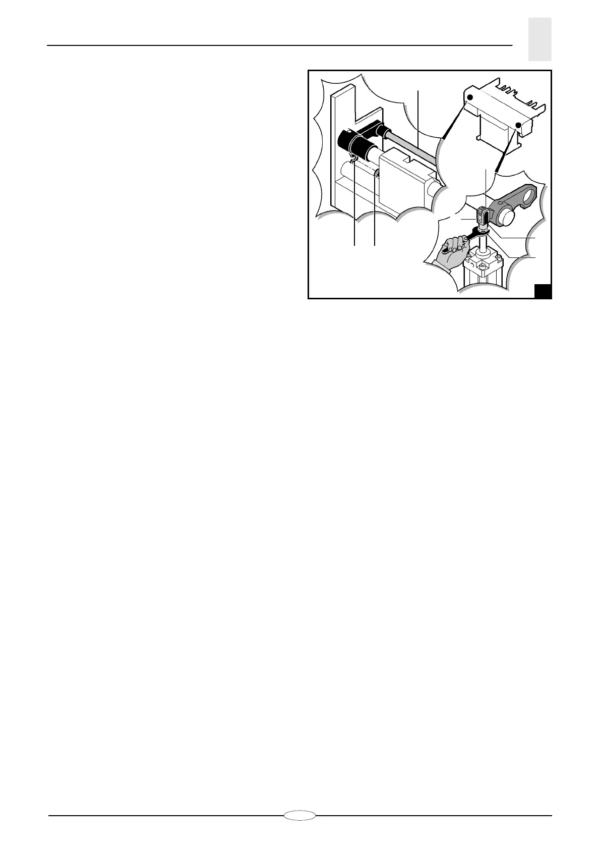
5.2.2 Bar pusher working position -
Adjustment
(fig. 2)
When the bar pusher
A
has been lowered, the groove
on lever
B
must be aligned with the carriage pin
C
.
To adjust the bar pusher working position:
– remove the rear guard;
– remove the pin
D
and pull the lever
E
;
– loosen the nut
F
. Then, either tighten or loosen the
fork pin
G
depending on what you need to do;
– tighten the nut
F
and fit the pin
D
again.
5.3. ADJUSTMENTS ACCORDING TO BAR TYPE
- FOREWORD
They include all the preliminary adjustments that must
be made according to the diameter, length and section
type of the bar to be machined.
5.3.1 Reduction sleeves - Diameter change-over.
5.3.2 Magazine inclination - Adjustment.
5.3.3 Bar selection - Adjustment.
5.3.4 Covering frame - Adjustment.
5.3.5 Guide lifting limit switch - Adjustment.
5.3.6 Bar pusher - Selection and installation.
5.3.7 Bar passage guide (optional) - Adjustment.
5.3.1 Reduction sleeves - Diameter change-over
To support bars in the lathe, it is advisable to insert
reduction sleeves into the spindle.
Their inner diameter shall be equal to the bar pusher
diameter + 1 mm.
Example:
to make sure that ø12 mm bar pusher never touches
the spindle inner part, the inner diameter of the spindle
liners must be at least 13 mm.