32
2
INSTALLATION PROCEDURE
302.061
As far as “BAR CHANGE-OVER” signal control is concerned, this option dif-
fers from option
1 - (RETURN)
.
Said signal controls more bar-pusher feeding movements, whenever they are
required by lathe during workpiece machining.
In this condition, the “BAR CHANGE” controls the feeding of the bar feeder
and disables its return. The bar feeder return depends on the “FEEDING” si-
gnal.
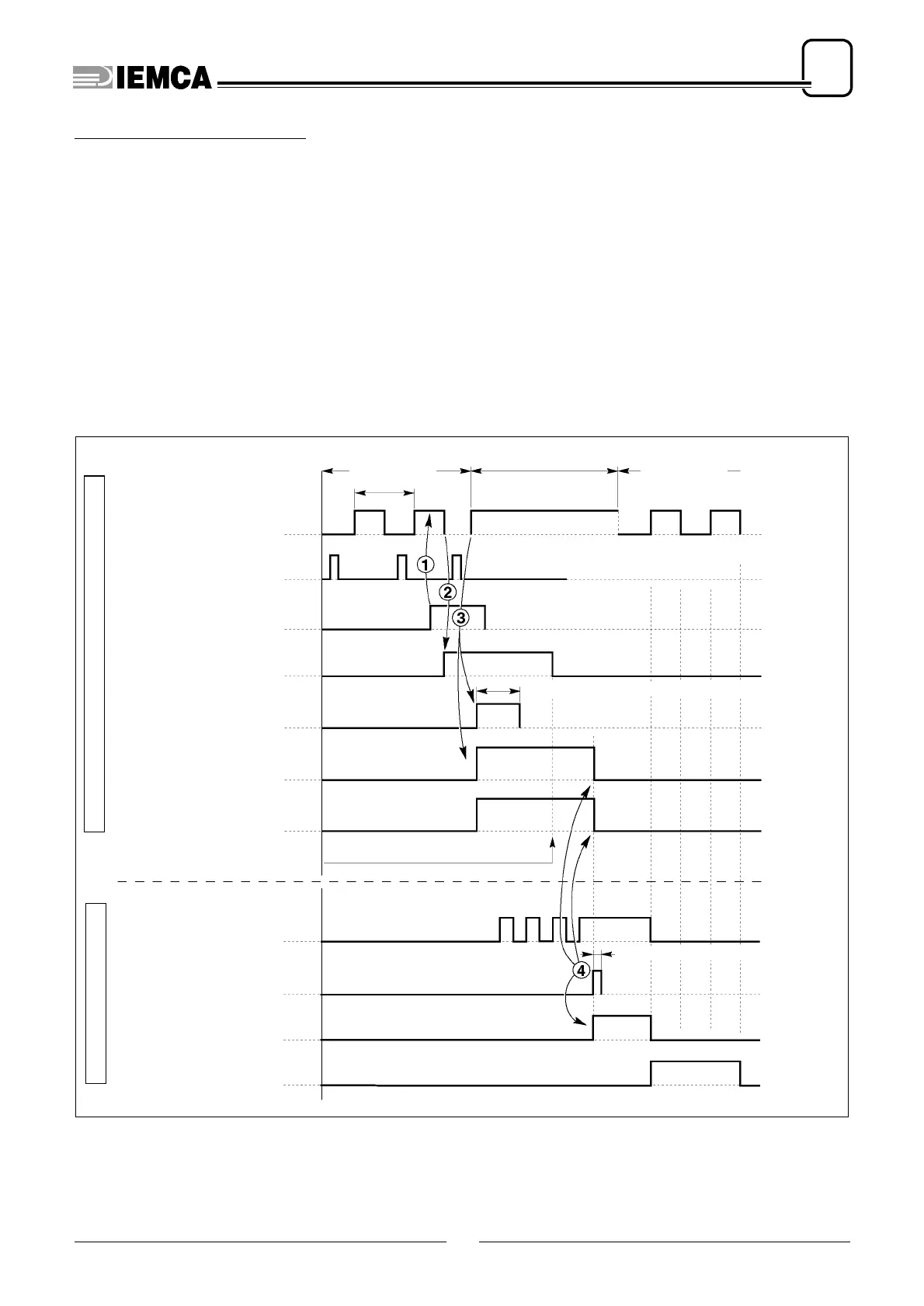
Interface signal cycle diagram
4-(FEEDING)
61.030 Ec.0
MACHINING
Feed (OPEN COLLET)
parameter
1
End of material detected by the encoder
K1
BAR END
K13
CYCLE STOP
K19B
CONTINUOUS CYCLE STOP
BAR CHANGE-OVER
BAR CHANGE-OVER CYCLE
t
(time adjustable through parameter 38)
t (time adjustable through parameter 37)
K15
CYCLE START
K10
1ST CYCLE DESACTIVATION
K10A
2ND CYCLE DESACTIVATION
K29
SPINDLE IMPULSES
CYCLE START
MACHINING
2nd feed
WORK-
PIECE
Bar feeder at the rear limit switch
SPINDLE STOP
K30
 Loading...