34
INSTALLERUSERMAINTENANCE TECHNICIANTECHNICAL DATA
Horizontal intake/exhaust assembly kits Ø 60/100 (Fig. 17)
1. Install the curve with ange (2) on the central hole of the appliance, positioning gasket (1) with the circular projections downwards in
contact with the appliance ange, and tighten using the screws contained in the kit.
2. Fit the Ø 60/100 (3) concentric terminal pipe with the male side (smooth) to the female side of the bend (2) up to the end stop, making
sure that the internal and external wall sealing plates have been tted; this will ensure sealing and joining of the elements making up
the kit.
C
13
5
4
3
1
2
17
e kit includes (Fig. 17):
N° 1 Gas ket (1)
N°1 Concentric bend Ø 60/100 (2)
N°1 Int./exhaust concentric terminal Ø 60/100 (3)
N°1 Internal wall sealing plate (4)
N°1 External wall sealing plate (5)
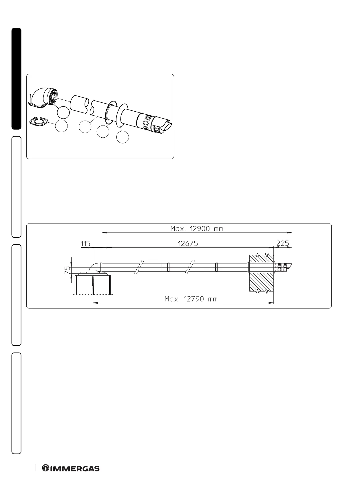
Extensions for Ø 60/100 horizontal kit. Kit assembly (Fig.18):
e kit with this conguration can be extended up to a max. horizontal length of 12.9 m including the terminal with grid and excluding
the concentric bend leaving the appliance.
In this case the special extensions must be requested.
is conguration corresponds to a resistance factor of 100.
Immergas also provides a Ø 60/100 simplied terminal, which in combination with its extension kits allows you to reach a maximum
extension of 11.9 metres.
C
13
18