35
INSTALLER
USERMAINTENANCE TECHNICIAN
TECHNICAL DATA
Horizontal intake/exhaust assembly kits Ø 80/125 (Fig. 19)
To install the kit Ø 80/125 one must use the anged adapter kit in order to install the Ø 80/125 ue system.
1. Install the anged adaptor (2) on the central hole of the appliance, positioning gasket (1) with the circular projections downwards in
contact with the appliance ange, and tighten using the screws contained in the kit.
2. Engage the bend (3) with the male side (smooth) to the end stop on the adapter (2).
3. Fit the Ø 80/125 (4) concentric terminal pipe with the male side (smooth) to the female side of the bend (3) (with lip seals) up to the end
stop, making sure that the internal (5) and external wall sealing plates (6) have been tted; this will ensure sealing and joining of the
elements making up the kit.
C
13
1
2
3
4
5
6
19
e adapter kit includes (Fig. 19):
N° 1 Gas ket (1)
N°1 Adapter Ø 80/125 (2)
e Ø 80/125 kit includes (Fig. 19):
N°1 Concentric bend Ø 80/125 at 87° (3)
N°1 Int./exhaust concentric terminal Ø 80/125 (4)
N°1 Internal wall sealing plate (5)
N°1 External wall sealing plate (6)
e remaining kit components must not be used
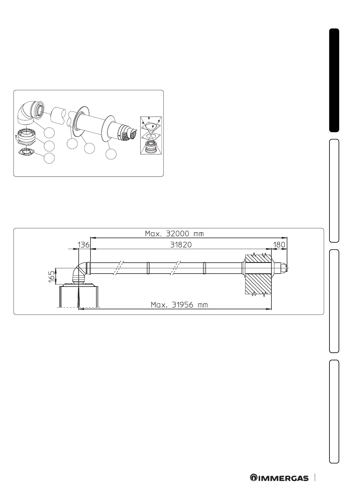
Extensions for Ø 80/125 horizontal kit. Kit assembly (Fig.20):
e kit with this conguration can be extended up to a max. length of 32 m, including the terminal with grid and excluding the concen-
tric bend leaving the appliance.
If additional components are assembled, the length equivalent to the maximum allowed must be subtracted.
In this case the special extensions must be requested.
C
13
20