38
INSTALLERUSERMAINTENANCE TECHNICIANTECHNICAL DATA
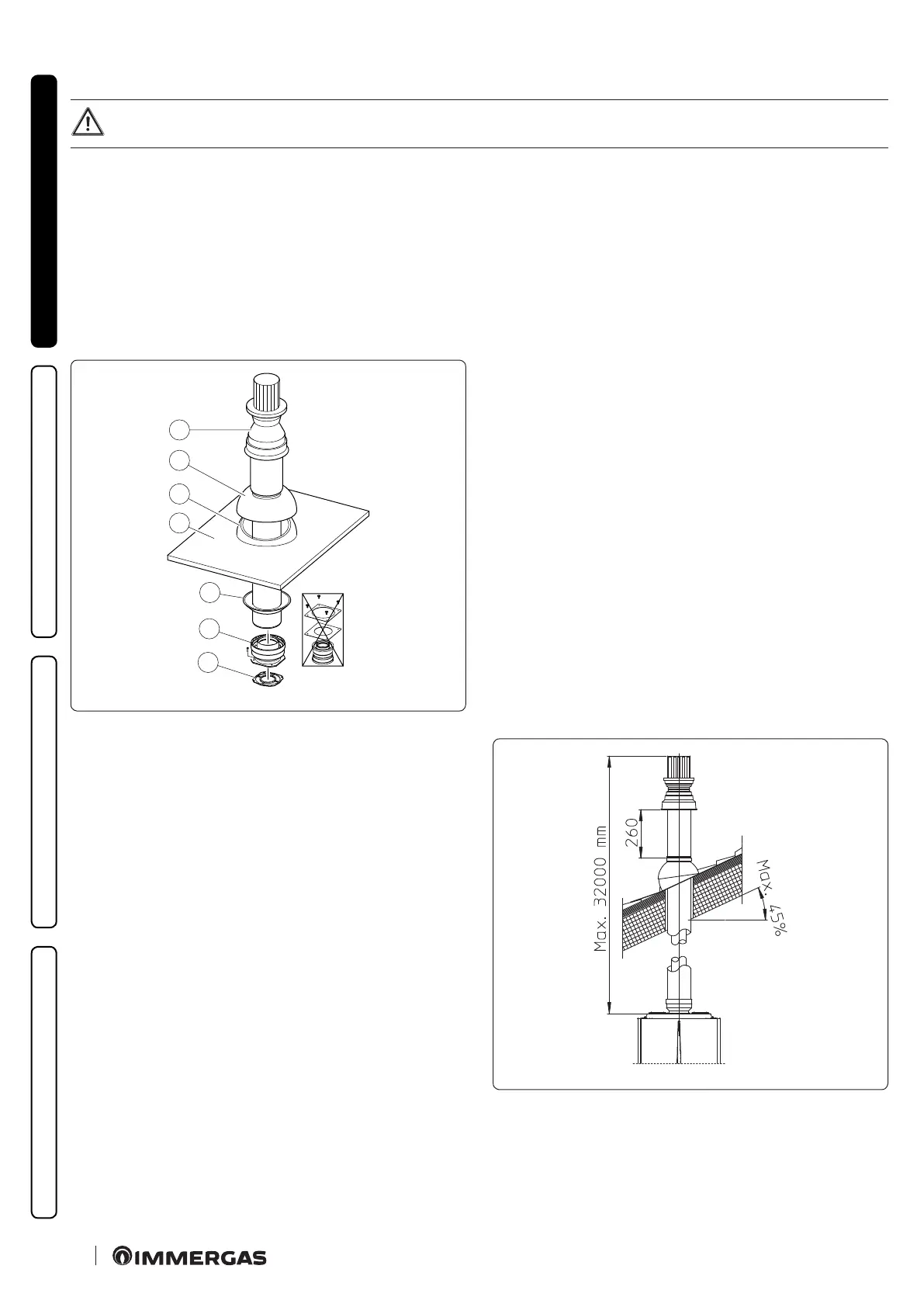
Vertical kit assembly with aluminium slate Ø80/125 (Fig. 23)
To install the kit Ø 80/125 one must use the anged adapter kit in order to install the Ø 80/125 ue system.
1. Install the concentric ange (2) on the ue exhaust of the appliance, positioning gasket (1) with the circular projections downwards in
contact with the appliance ange.
2. Tighten the concentric ange with the screws in the kit.
Imitation aluminium slate installation:
3. Tighten the concentric ange with the screws in the kit.
4. Replace the slates with the aluminium sheet (4), shaping it to ensure that rainwater runs o.
5. Position the xed half-shell (5) on the aluminium slate;
6. Insert the intake-exhaust terminal (7);
7. Fit the Ø 80/125 concentric terminal pipe with the male side (smooth) to the female side of the adapter (1) (with lip seals) up to the end
stop, making sure that the wall sealing plate (3) has been tted; this will ensure sealing and joining of the elements making up the kit.
C
33
1
2
3
4
5
6
7
23
e adaptor kit includes (Fig. 23):
N° 1 Gas ket (1)
N°1 Adapter Ø 80/125 (2)
e Ø 80/125 kit includes (Fig.23):
N°1 Wall sealing plate (3)
N°1 Aluminium slate (4)
N°1 Fixed half-shell (5)
N°1 Mobile half-shell (6)
N°1 Concentric intake/exhaust pipe Ø 80/125 (7)
e remaining kit components must not be used
Extensions for Ø 80/125 vertical kit (Fig. 24)
e kit with this conguration can be extended to a max. straight
vertical length of 32 m, including the terminal. If additional com-
ponents are assembled, the length equivalent to the maximum al-
lowed must be subtracted. In this case the special extensions must
be requested.
C
33
24