42
INSTALLERUSERMAINTENANCE TECHNICIANTECHNICAL DATA
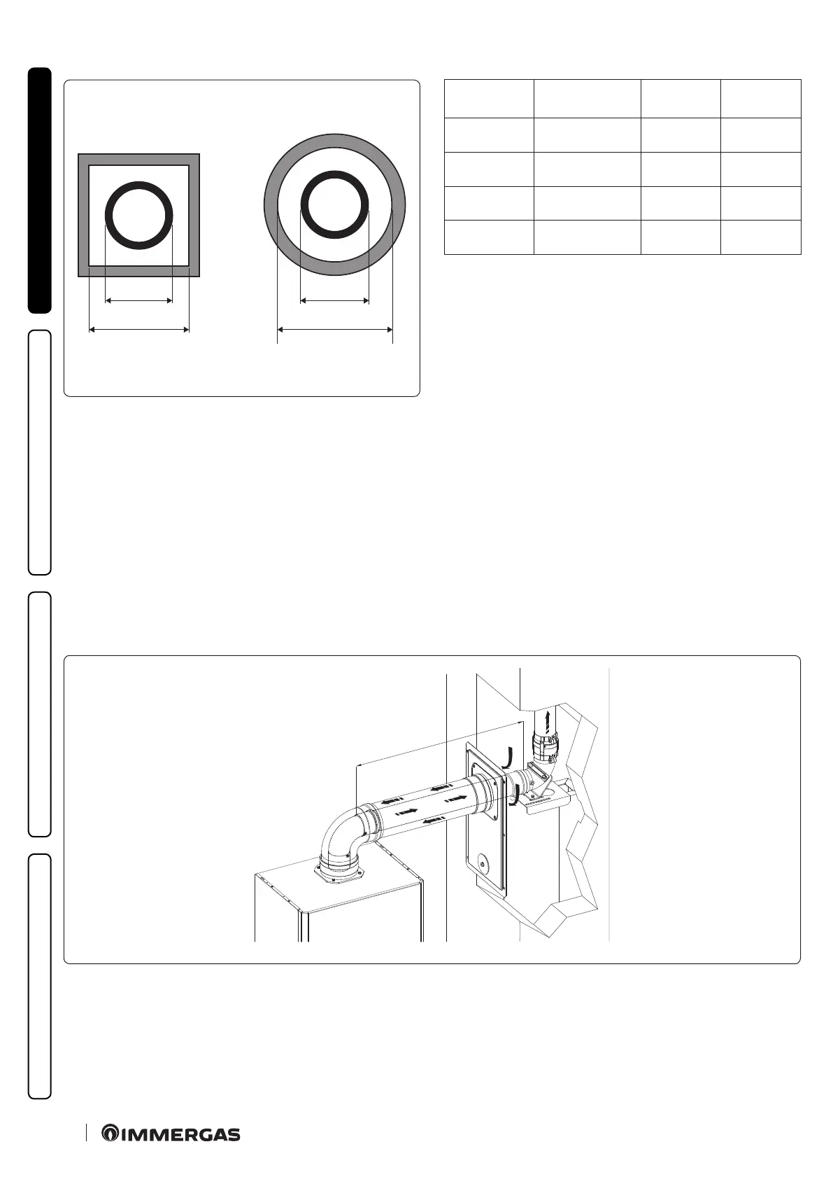
A
B
A
C
29
Ducting
ADAPTOR
(A) mm
SHAFT
(B) mm
SHAFT
(C) mm
Ø 60
Rigid
66 106 126
Ø 50
Flexible
66 106 126
Ø 80
Rigid
86 126 146
Ø 80
Flexible
103 143 163
Technical data
e dimensions of the shas must ensure a minimum gap between the outer wall of the smoke duct and the inner wall of the sha: 30 mm
for circular section shas and 20 mm in the event of a square section sha (Fig. 29).
Maximum 2 changes of direction are allowed on the vertical section of the ue system with a maximum clearance angle of 30° with re-
spect to the vertical.
e maximum vertical extension using a Ø 60 ducting system is 13 m, the maximum extension includes 1 bend Ø 60/100 at 90°, 1 m of
horizontal pipe 60/100, 1 90° Ø 60 ducted bend and the roof terminal for ducting.
e maximum vertical extension using a rigid Ø 80 ducting system is 30 m; the maximum extension includes 1 adapter Ø 60/100 to Ø
80/125, 1 87° bend Ø 80/125, 1 m of horizontal pipe Ø 80/125, 1 90° Ø 80 ducted bend and the roof terminal for ducting.
To determine the C
93
ue system in congurations other than that described (Fig.30) one must consider the following head losses:
- 1 m of concentric pipe Ø 80/125 = 1.8 m of rigid ducted pipe Ø 80 and 0.7 m of exible ducted pipe Ø 80;
- 1 Ø80 bend at 87° = 2.1 m of rigid ducted pipe Ø 80 and 0.9 m of exible ducted pipe Ø 80;
Consequently one must subtract the equivalent length of the part added to the 28 m available.
C
93
X
30