1 - 22
Transpector MPH Operating Manual
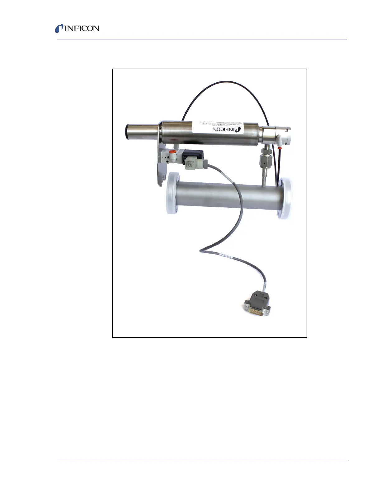
9 The fully assembled HPR flange is shown in Figure 1-15.
Figure 1-15 Fully assembled HPR flange
1.18.2 Installing the Extension Flange, Sensor, and Electronics Module
The extension flange and sensor are installed as usual, except one of the bolts that
connect the sensor to the extension flange must go through the HPR mounting
bracket. Refer to Hardware Installation, section 1.16 on page 1-9.
1.18.3 Connecting the HPR Valve Control Cable
The HPR solenoid is powered by the Transpector MPH Auxilliary I/O connection.
Connect the 15-Pin D-Sub connection to the Aux I/O port of the Transpector MPH
electronics module.