Specification Value
Type of inputs Non-isolated
Differential or single ended
ESD protected
Number of inputs 3 (A, B and Index)
ESD capability IEC 61000-4-2 (ESD) ± 15 kV (air), ± 8 kV (contact)
IEC 61000-4-4 (EFT) 40 A (5/50 ns)
Nominal voltage range 0 ~ 5 V
Maximum voltage range -0.5 ~ 5.5 V
Maximum working frequency 10 MHz
Termination resistor 120 Ω (between ENC_x+ and ENC_x-)
Bias resistors ENC_x+ (positive input) 2 kΩ to 5 V
ENC_x- (negative input) 1 kΩ to 2.5 V (equivalent)
For encoder signal reception, an analog differential line receiver with an hysteresis comparator is used.
The high signals (ENC_A+, ENC_B+ and ENC_Z+) are pulled up to +5 V, and the low signals (ENC_A-, ENC_B-
and ENC_Z-) are biased to 2.5 V. This arrangement let user to connect either open collector and totem pole
single-ended output encoders, or differential output encoders.
The encoder interface accepts an RS-422 differential quadrature line driver signal in the range of 0 V to 5 V
up to 10 MHz. When single ended encoder is connected, only high signals (ENC_A+, ENC_B+ and ENC_Z+)
must be used.
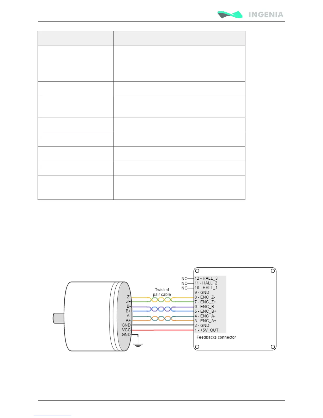
Next figures illustrate how to connect a differential and a single ended encoder to the Pluto Servo Drive.
Refer to for more information about connections and wires.Feedback wiring recommendations