16 Programming peripherals
Anti-intrusion control panels
In the case of a reader simulated by the Air2-BS200 transceiver, the parameters of the
wireless system will be available in the section reserved for wireless receivers (refer to
paragraph 3-6 Wireless transceivers).
3-3
Expansions
3-3-1
Enrolling expansions
Via software Once the solution for the system to be designed has been opened, click on the System
Layout button on the menu on the left. Then click on the “Add device to BUS” button in the
section on the right.
A window will open for the selection of the expansions to be configured and then added to the
configuration.
In the section on the left, the number is increased in correspondence with the expansions
button.
To remove an expansion from the structure, access the programming section by clicking on
the relative button in the menu on the left then, from the list displayed, click on the Delete
button in correspondence with the line of the expansion in question.
Via keypad
Type-in Code
(Installer PIN)
, PROGRAMMING Expansions, Enablements
In this section it is possible to add/remove expansions from the configuration, by means of
keys and .
WIRELESS
EXPANSIONS
During the enrolling phase the Air2-BS200 wireless transceiver will be integrated into the
Prime system by simulating:
• a reader, with an address programmed via the module itself (ADD), by means of buttons
P1 and P2 on the PCB (for details refer to the Module manual)
• up to 10 expansion boards, at addresses ADD, ADD+1, ... ADD+9, to manage the
terminals to be configured via the “System Layout” section of the Prime/STUDIO software.
Via software In order to classify an expansion as a “wireless” expansion, it must first be configured as
described above, as per a hardwired expansion.
Once configured, click on the System Layout button, the section on the right will show the
diagram of the terminals of the entire system.
Right click on the expansion previously added to the configuration and select “Wireless” to
classify it as such. The “Wireless” symbol will appear on the expansion image. The
configuration is completed by enrolling the wireless devices.
Via keypad
Type in Code
(Installer)
, PROGRAMMING Terminals,
select an expansion terminal
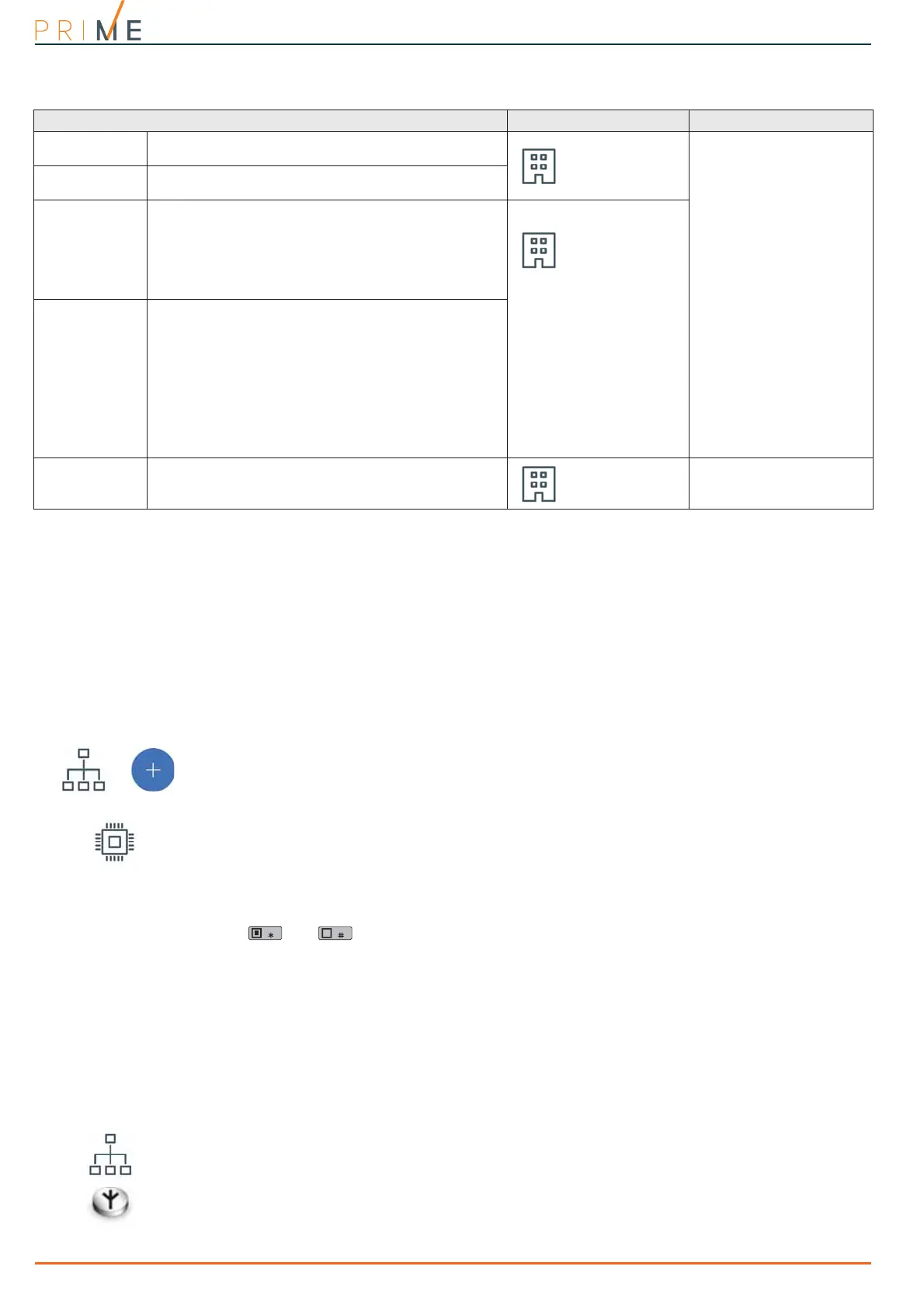
Table 3-7: Parameters of single reader
Parameter Software section Installer menu section
Description
This is the name used to identify the reader,
customizable by the installer.
Configured
readers, selected
reader
Readers, Chooseperiph-
eral, "reader"
Partitions
Section for the selection of the partitions the reader can
operate on.
Type
It is possible to assign a shortcut type, selectable from
those available, to each of the LEDs (refer to Appendix
B, Shortcuts by default).
The type of activatable shortcut is to be chosen in
accordance with the reader model, whether standalone
or integrated, as the activation of some shortcuts
depends on the presence of a keypad with a display.
Configured
readers, selected
reader, Shortcut
Readers, Chooseperiph-
eral, "reader", Short-
cut, Type
Parameter
It is necessary to specify a further parameter for each
shortcut:
• Execute Arm/Disarm, the parameter is one of the
scenarios
• Activate output, the parameter is an output
• Deactivate output, the parameter is an output
• Activate output scenario, the parameter is one of
the scenarios
• Panic, the parameter will be one of the panic events
• Access shortcuts to menus and data viewing on
keypad displays, the parameter is the reference
access code
Valid key at
reader
Button to access directly the programming section of
the “Valid key at reader” event
Configured
readers, selected
reader
Events, Valid-
KeyAtReader