Programming manual
Monitoring the control panel 93
There are two keys to obtain specific information for each device (address, firmware version,
operating voltage, presence of faults, etc.):
- Update, for a data update
- Continuous, for continuous reading of the data in real time
In addition, via tooltip (passing over the icon with the mouse pointer) the device model is
provided and if it is present or not.
21-7
Monitoring sounder/flashers
The monitoring phase on the sounder/flashers, both wireless and on the I-BUS, provides
feedback relating to the status sounder/flashers and their descriptions.
Via softwareClick on the Monitoring button on the menu bar, then go to the “Peripherals, Sounder/
flashers” section.
The information relative to each sounder/flasher is shown after the respective icon. If the
sounder/flasher is configured the icon will not be blanked out and will be accompanied by its
description and the status, fault and tamper icons, as follows:
WIRELESS
SOUNDERS/
FLASHERS
The programming section of the wireless sounder/flashers allows you view their status.
Via softwareClick on the Sounder/flashers button on the menu on the left, the “Programming,
Configured sounders/flashers” section on the right will show a list of configured sounder/
flashers. By selecting a sounder/flasher with the “Wireless” attribute, the “Real time” sub-
section will allow you to view the sounder/flasher status.
In this section, the monitoring window lists the parts of the sounder/flasher whose status is
represented by icons/LED:
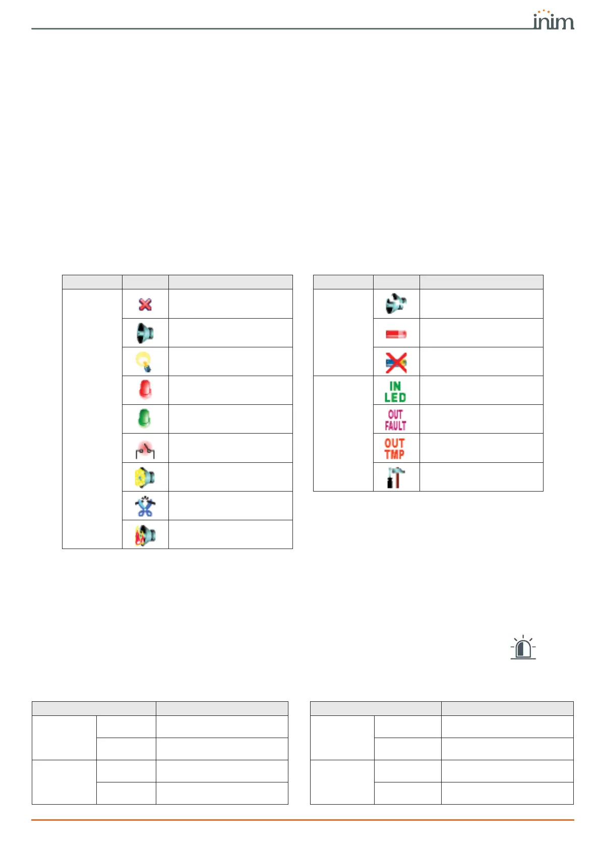
Table 21-2: Sounder/flasher icons
Category Icon Notification Category Icon Notification
Alarms
Sounder/flasher loss
Faults
Sounder broken
Sounder active Low battery
Flasher active Battery fault
STATUS LED On
Status
LED input activated
PRG LED On Output FAULT active
Sounder/flasher tamper Output TAMPER active
Foam tamper protection
activated
Sounder/flasher undergoing
programming
Wire cutting
Blow torch protection
activated
Table 21-3: Wireless sounder/flasher status LEDs
LED Status LED Status
Tamper
Green
Sounder/flasher not in tamper
status
Flasher active
Green
Visual signalling Off
Red
Sounder/flasher in tamper
status (open or dislodged)
Red
Visual signalling On
Antifoam
Green
Foam level below alarm
signalling threshold
STATUS LED
ON
Green
STATUS LED off
Red
Foam level above alarm
signalling threshold
Red
STATUS LED On