94 Monitoring the control panel
Anti-intrusion control panels
Instead, the “Wireless monitoring” sub-section provides the Start button that starts a
monitoring on the variation of the signal transmitted by the device and background noise
detected over time.
21-8
Monitoring Flex5/DAC
expansions
The software monitoring function allows you to view the status of the outputs of all the
connected Flex5/DAC expansions and to work on them.
Via software Click on the Monitoring button on the menu bar, then go to the “Peripherals, DAC peripheral”
section.
In this section you must first select the expansion, form those configured, by entering the
relative address in the appropriate field. After clicking-on the Start monitoring button this
section will show the following:
• Status of each of the 5 outputs on the expansion:
•• power absorbed by the load, phase shift or power factor and current for alternating
current loads at mains voltage
•• Percentage of the supplied power with respect to the maximum possible, measured
exclusively for dimmable loads.
• Buttons for the activation or deactivation of each single output or to change the voltage
supplied to the dimmer output (this operation is allowed only after the entry of a valid user
code)
• Voltage supplied to the expansion
21-9
Monitoring the power supply
The software has a section for monitoring the power supplies, through LEDs with the relative
colours and values shown in the readings.
Via software Click on the Monitoring button on the menu bar, then go to the “Peripherals, Power” section.
After clicking-on the Start monitoring button this section will show:
• data relating to the power supplied to the control panel
•• primary power supply
•• power and secondary power supply
•• power supply module
•• battery
• the data relating to the power the control panel supplies to the devices in the field:
•• voltages and currents on the “AUXx” terminals
•• voltage and current on the I-BUS
Battery fault
Green
Battery charged
PRG LED ON
Green
PRG LED off
Red
Battery charge low (below
40%)
Red
PRG LED On
Sounder
active
Green
Audible signalling Off
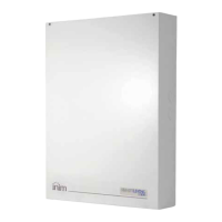
Signal recep-
tion level
This series of notches
represents the reception level
of the wireless signal of the
device as received by the Air2-
BS200 transceiver.
Red
Audible signalling On
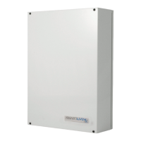
Battery level
Percentage of charge of the
sounder/flasher battery
Table 21-3: Wireless sounder/flasher status LEDs