2.5.3.3. Configuration Pins I/O Standard, Drive Strength, and IBIS Model
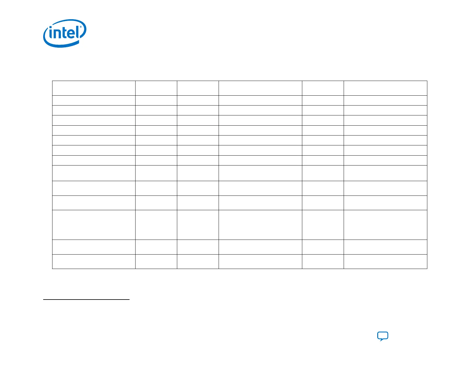
Table 6. Intel Agilex Configuration Pins I/O Standard, Drive Strength, and IBIS Model
Configuration Pin Function Location Direction I/O Standard Drive Strength
(mA)
Weak Pull-Up/Pull-Down
TDO
SDM I/O bank Output 1.8 V LVCMOS 8 Weak pull-up
TMS
SDM I/O bank Input Schmitt Trigger Input — Weak pull-up
TCK
SDM I/O bank Input Schmitt Trigger Input — Weak pull-down
TDI
SDM I/O bank Input Schmitt Trigger Input — Weak pull-up
nSTATUS
SDM I/O bank Output 1.8V LVCMOS 8 Weak pull-up
OSC_CLK_1
SDM I/O bank Input Schmitt Trigger Input — Weak pull-down
nCONFIG
SDM I/O bank Input Schmitt Trigger Input — Weak pull-up
SDM_IO[0],SDM_IO[8],
SDM_IO[16]
SDM I/O bank I/O Schmitt Trigger Input or 1.8 V
LVCMOS
8 Weak pull-down
SDM_IO[7:1],SDM_IO[15:9]
SDM I/O bank I/O Schmitt Trigger Input or 1.8 V
LVCMOS
— Weak pull-up
AVST_CLK
SDM Shared
GPIO bank
Input 1.2 V LVCMOS — —
AVST_READY
SDM Shared
GPIO bank
Output 1.2 V LVCMOS Series 34 ohm
on-chip
termination
(OCT) without
calibration
(4)
—
AVST_VALID
SDM Shared
GPIO bank
Input 1.2 V LVCMOS — —
AVST_DATA
SDM Shared
GPIO bank
Input 1.2 V LVCMOS — —
You can download the IBIS models from the IBIS Models for Intel Devices web page. The Intel Quartus Prime software does
not support IBIS model generation for configuration pins in the current release.
(4)
Slow slew rate signal
2. Intel Agilex Configuration Details
UG-20205 | 2019.10.09
Intel
®
Agilex
™
Configuration User Guide
Send Feedback
36