221
Code system
· 1 start bit
· 7 or 8 digital bit, the minimum valid bit can be sent firstly. Every 8 bit frame includes two
hex characters (0...9, A...F)
· 1 even/odd check bit . If there is no checkout, the even/odd check bit is inexistent.
· 1 end bit (with checkout), 2 Bit(no checkout)
Error detection field
· CRC
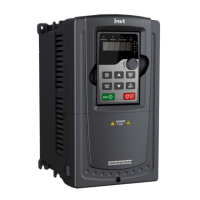
The data format is illustrated as below:
11-bit character frame (BIT1~BIT8 are the digital bits)
Start bit BIT1
In one character frame, the digital bit takes effect. The start bit, check bit and end bit is used
to send the digital bit right to the other device. The digital bit, even/odd checkout and end bit
should be set as the same in real application.
The MODBUS minimum idle time between frames should be no less than 3.5 bytes. The
network device is detecting, even during the interval time, the network bus. When the first
field (the address field) is received, the corresponding device decodes next transmitting
character. When the interval time is at least 3.5 byte, the message ends.
The whole message frame in RTU mode is a continuous transmitting flow. If there is an
interval time (more than 1.5 bytes) before the completion of the frame, the receiving device
will renew the uncompleted message and suppose the next byte as the address field of the
new message. As such, if the new message follows the previous one within the interval time
of 3.5 bytes, the receiving device will deal with it as the same with the previous message. If
these two phenomena all happen during the transmission, the CRC will generate a fault
message to respond to the sending devices.
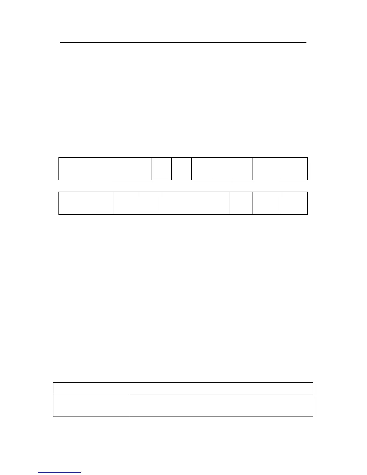
The standard structure of RTU frame:
START T1-T2-T3-T4(transmission time of 3.5 bytes)
ADDR
C
 Loading...