30
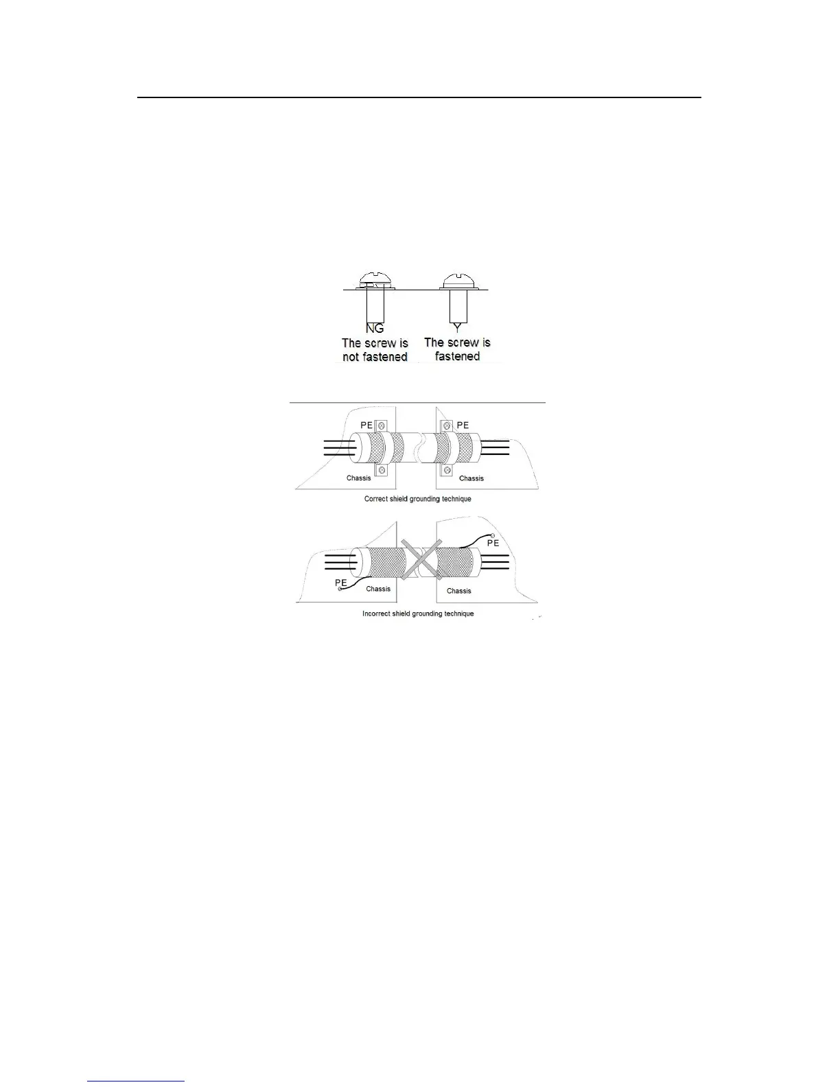
2. Strip the motor cable and connect the shield to the grounding terminal of the inverter by
360 degree grounding technique. Connect the phase conductors to U, V and W terminals
and fasten.
3. Connect the optional brake resistor with a shielded cable to the designated position by the
same procedures in the previous step.
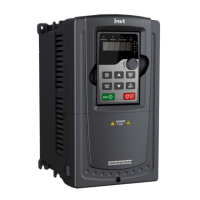
4. Secure the cables outside the inverter mechanically.
Fig 4-18 Correct installation of the screw
Fig 4-19 360 degree grounding technique
 Loading...