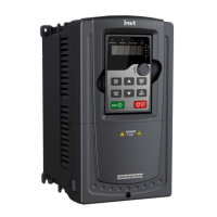
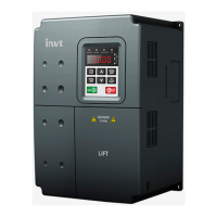
Description
HDO
1. Switch input:200mA/30V
2. Output frequency range:0~50kHz
COM +24V common terminal
CME
Common terminal of HDO and Y1, short-connected with COM in
factory
Y1
1.Swtich capability:200mA/30V
2.Output frequency range:0~1kHz
485+
485 communication interface and 485 differential signal interface
If it is the standard 485 communication interface, please use
twisted pairs or shield cable.
485-
4.3.6 Input/Output signal connection figure
Please use U-shaped contact tag to set NPN mode or PNP mode and the internal or external
power supply. The default setting is NPN internal mode.
Fig 4-22 U-shaped contact tag
If the signal is from NPN transistor, please set the U-shaped contact tag between +24V and
PW as below according to the used power supply.

 Loading...


