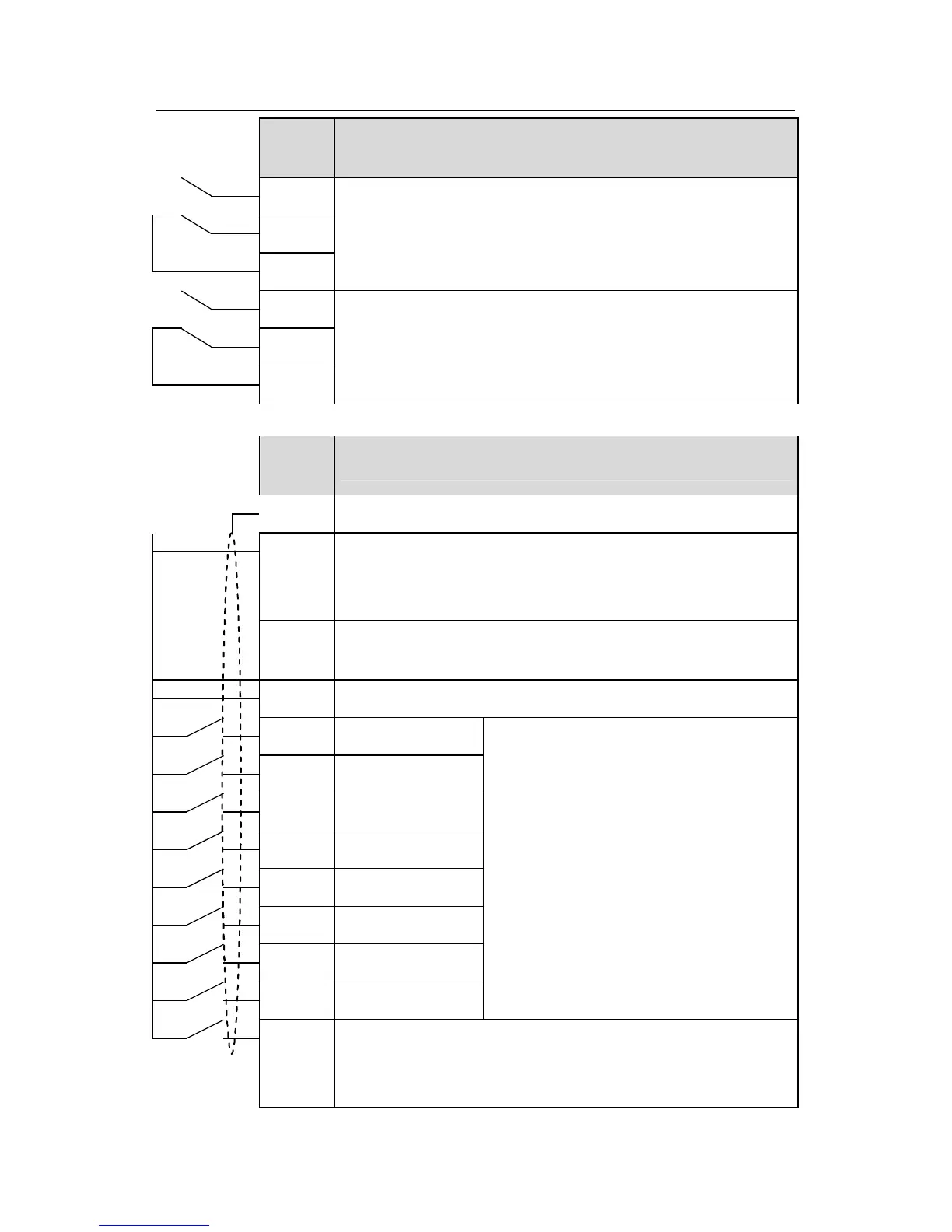
RO1 relay output, RO1A NO, RO1B NC, RO1C common terminal
RO2 relay output, RO2A NO, RO2B NC, RO2C common terminal
PW
Provide the input switch working power supply from external to
internal.
Voltage range: 12~24V
24V
The inverter provides the power supply for users with a maximum
output current of 200mA
COM +24V common terminal
S1 Switch input 1
1. Internal impedance:3.3kΩ
2. 12~30V voltage input is available
3. The terminal is the dual-direction input
terminal supporting both NPN and PNP
4. Max input frequency:1kHz
5. All are programmable digital input
terminal. User can set the terminal function
through function codes.
S2 Switch input 2
S3 Switch input 3
S4 Switch input 4
S5 Switch input 5
S6 Switch input 6
S7 Switch input 7
S8 Switch input 8
HDI
Except for S1~S8, this terminal can be used as high frequency
input channel.
Max. input frequency:50kHz
 Loading...