Goodrive270 series VFD for fan and pump Basic operation guidelines
-100-
time for choose.
After the set PLC completes one cycle (or one step), one ON signal can be output by the multifunction
relay.
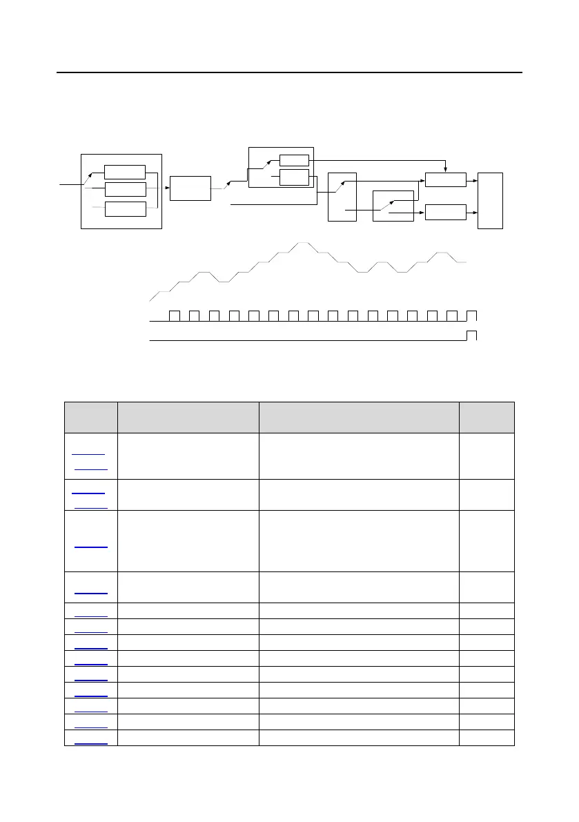
Setup of running
parameters of each
PLC stage
Restart running
after the first
section
Continue running at
the frequency when
interruption occurred
Stop after running
once
Keep running with
the final value after
running once
Cyclic running
0
1
2
P10.00 (Simple PLC mode)
PLC mode
0
1
0
1
0
1
Normal running
P10.01 (Simple PLC memory selection)
Without power-
failure memory
With power-
failure
memory
P10.36
(PLC restart mode)
P17.00
Power failure during
running
Terminal function 23
Simple PLC stop reset
Set frequency
Digital output 16
Simple PLC state completed
Digital output 17
Simple PLC cycle completed
Related parameter list:
Name Description Default
P05.01±
P05.06
Digital input function selection
23: Simple PLC stop reset
24: Pause simple PLC
P06.01±
Digital output function
16: Simple PLC stage reached
17: Simple PLC cycle reached
P10.00 Simple PLC mode
0: Stop after running once
1: Keep running with the final value after
running once
0
P10.01
Simple PLC memory
0: Without power-failure memory
1: With power-failure memory
0
 Loading...