Goodrive270 series VFD for fan and pump Function parameter list
-131-
Name Description Default
P01.27, and P01.28 accordingly.
P01.06
Time of starting
segment of ACC S
curve
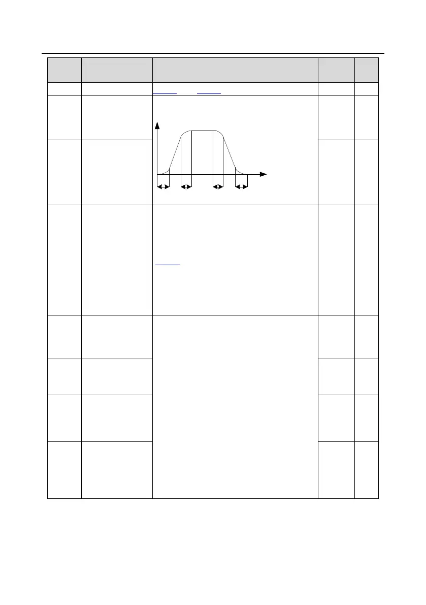
The curvature of S curve is determined by the
ACC range and ACC/DEC time.
Output frequency f
Time t
t1 t2 t3 t4
t1=P01.06
t2=P01.07
t3=P01.27
t4=P01.28
0.1s Ƽ
P01.07
Time of ending
segment of ACC S
curve
0.1s Ƽ
P01.08 Stop mode
0: Decelerate to stop. After a stop command
takes effect, the VFD lowers output frequency
based on the DEC mode and the defined DEC
time; after the frequency drops to the stop speed
(
P01.15), the VFD stops.
1: Coast to stop. After a stop command takes
effect, the VFD stops output immediately; and
the load coasts to stop according to mechanical
inertia.
0 ƻ
P01.09
DC braking for stop
Starting frequency of DC braking for stop: During
the deceleration to stop, the VFD starts DC
braking for stop when running frequency reaches
the starting frequency determined by P01.09.
Wait time before DC braking: The
VFD blocks the
output before starting DC braking. After this wait
time, DC braking is started so as to prevent
overcurrent caused by DC braking at high speed.
DC braking current for stop: It indicates the
applied DC braking energy. Stronger current
indica
tes greater DC braking effect.
DC braking time for stop: It indicates the hold
time of DC braking. If the time is 0, DC braking is
invalid, and the VFD decelerates to stop within
the specified time.
0.00Hz ƻ
P01.10
Demagnetization
time
0.00s ƻ
P01.11
DC braking current
for stop
0.0% ƻ
P01.12
stop
0.00s ƻ
 Loading...