Goodrive270 series VFD for fan and pump Function parameter list
-159-
Name Description Default
STOP/RST stop during terminal control. (See
P07.04.)
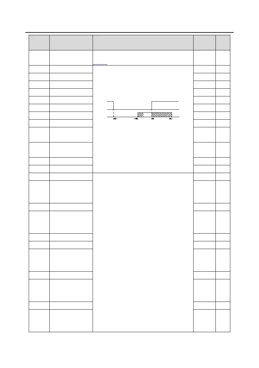
Used to specify the delay time corresponding to
the electrical level changes when the
programmable input terminals switch on or
switch off.
Si electrical
level
Si valid
Invalid Invalid
Switch-on
delay
Switch-off
delay
Valid
±50.000s
Note: After a virtual termina
l is enabled, the
state of the terminal can be changed only in
communication mode. The communication
address is 0x200A.
ƻ
ƻ
ƻ
ƻ
ƻ
ƻ
ƻ
ƻ
P05.20
HDIA switch-on
0.000s ƻ
P05.21
HDIA switch-off
0.000s ƻ
Used to define the relationship between the
analog input voltage and its corresponding
setting. When the analog input voltage exceeds
the range from the upper limit to the lower limit,
the upper limit or lower limit is used.
analog input is current input, 0mA±
20mA current corresponds to 0V
±10V voltage.
In different applications, 100.0% of the analog
setting corresponds to different nominal values.
See the descriptions of each application section
for details.
ure illustrates the cases of
ƻ
P05.25
Corresponding
setting of AI1 lower
0.0% ƻ
ƻ
P05.27
Corresponding
setting of AI1 upper
limit
100.0% ƻ
ƻ
ƻ
P05.30
Corresponding
setting of AI2 lower
-100.0% ƻ
ƻ
P05.32
Corresponding
setting of AI2 middle
value 1
0.0% ƻ
ƻ
P05.34
Corresponding
setting of AI2 middle
value 2
0.0% ƻ
 Loading...