EasyManuals Logo

INVT GD270-030-4 User Manual

INVT GD270-030-4
336 pages
To Next Page IconTo Next Page
To Previous Page IconTo Previous Page
Page #22 background imageLoading...
Page #22 background image
Goodrive270 series VFD for fan and pump Product overview
-12-
7
11
9
8
6
10
1213
3
4
1 5
2
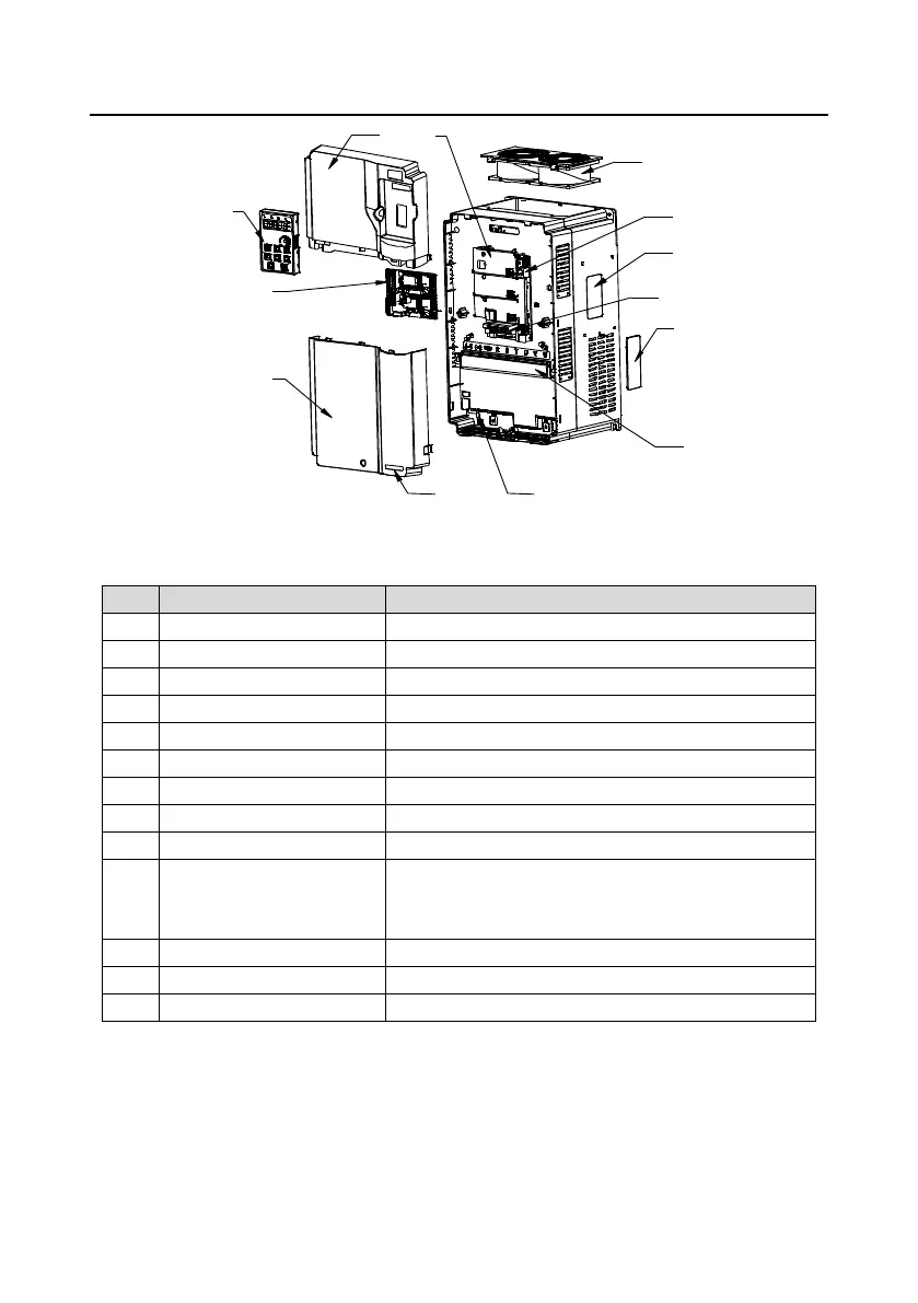
Figure 3-5 Structure diagram
No.
Name
Description
1
Upper cover
Protects internal components and parts.
2
Keypad
For details, see section 5.4 Operation procedure.
3
Lower cover
Protects internal components and parts.
4
Expansion card
Optional. For details, see Appendix A Expansion card.
5
Baffle of control board
Protects the control board and install expansion card.
6
Cooling fan
For details, see chapter 8 Maintenance.
7
Keypad interface
Connects the keypad.
8
Nameplate
For details, see chapter 3 Product overview.
9
Control circuit terminals
For details, see chapter 4 Installation guidelines.
10
Cover plate of heat emission
hole
Optional. Cover plate can upgrade protection level,
however, as it will also increase internal temperature,
derated use is required.
11
Main circuit terminal
For details, see chapter 4 Installation guidelines.
12
POWER indicator
Power supply indicator
13
GD270 product series label
For details, see section 3.5 Model designation code.

Table of Contents

Questions and Answers:

Question and Answer IconNeed help?

Do you have a question about the INVT GD270-030-4 and is the answer not in the manual?

INVT GD270-030-4 Specifications

General IconGeneral
BrandINVT
ModelGD270-030-4
CategoryWater Pump
LanguageEnglish

Related product manuals