Goodrive270 series VFD for fan and pump Installation guidelines
-19-
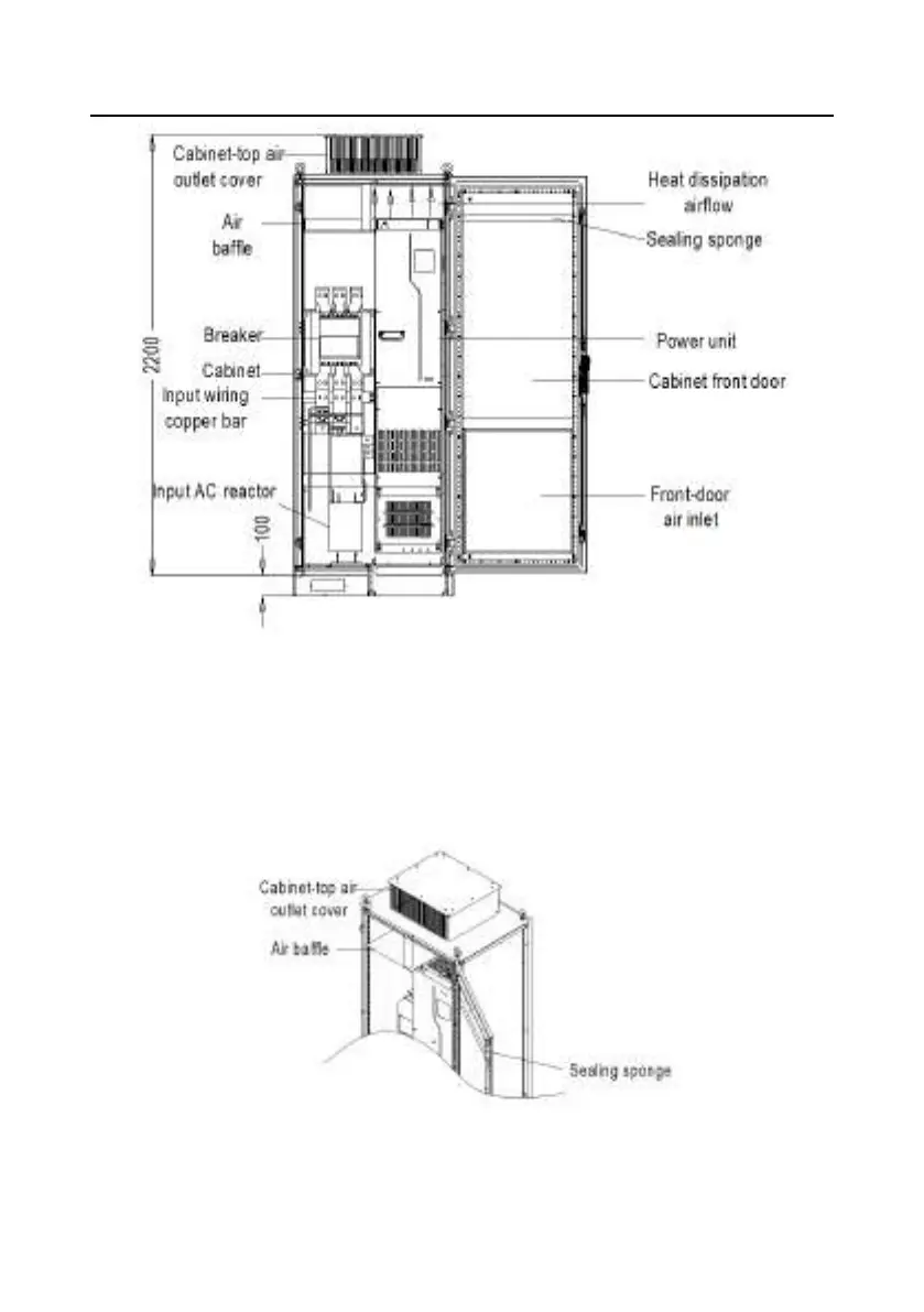
Figure 4±7 Diagram of mounting the VFD in a direct exhaust cabinet
As shown in Figure 4±8, the air duct of VFD must be isolated within the cabinet to prevent the hot air
in the VFD outlet from circulating within the cabinet, and the air baffle design for isolation ensures that
the hot air is discharged from the cooling holes at the top of cabinet.
Note: A 40X40 sealing sponge must be used at the position corresponding to the air baffle in
the front door panel, which prevents air duct short circuit.
Figure 4±8 Diagram of air baffle design
 Loading...