Goodrive270 series VFD for fan and pump Basic operation guidelines
-77-
0
1
2
3
4
5
6
7
8
9
10
11
Keypad
AI1
PROFIBUS\CANopen
MODBUS
PID
Multi-step speed
Simple PLC
HDI
AI3
AI2
Ethernet
UP/DOWN terminal
P08.44 tens setup
(frequency control
selection)
P17.14
Digital
adjustment
value of
keypad
P08.44 ones
(UP/DOWN terminal
control setting)
0
P00.03
1
A
frequency
command
(max. output
frequency)
0
UP/DOWN enable
0
Valid
Invalid
Valid
Invalid
Terminal function 12
Clear frequency
increase/decrease setup
Terminal function 33
Clear frequency
increase/decrease setup
temporarily
0
0
1
2
3
4
5
6
7
8
9
10
11
Keypad
AI1
PROFIBUS\CANopen
MODBUS
PID
Multi-step speed
Simple PLC
HDIA
AI3
AI2
Ethernet
P00.06
(A frequency command
selection)
P00.07
(B frequency command
selection)
P00.09
(combination mode of setup
source)
P00.05 (lower limit of running
frequency)
P17.00
Set
frequency
A
B
A+B
A-B
Max˄AˈB˅
Min˄AˈB˅
+
+
P17.02
Ramps reference
frequency
P00.08 (B frequency command reference
object selection)
Frequency set by keypad
0
1
2
3
4
5
P00.10
P00.10
Frequency set by keypad
P00.04 (upper limit of running
frequency)
Pulse string AB
HDIB
EtherCat/Profinet
PLC card
Pulse string AB
HDIB
EtherCat/Profinet
PLC card
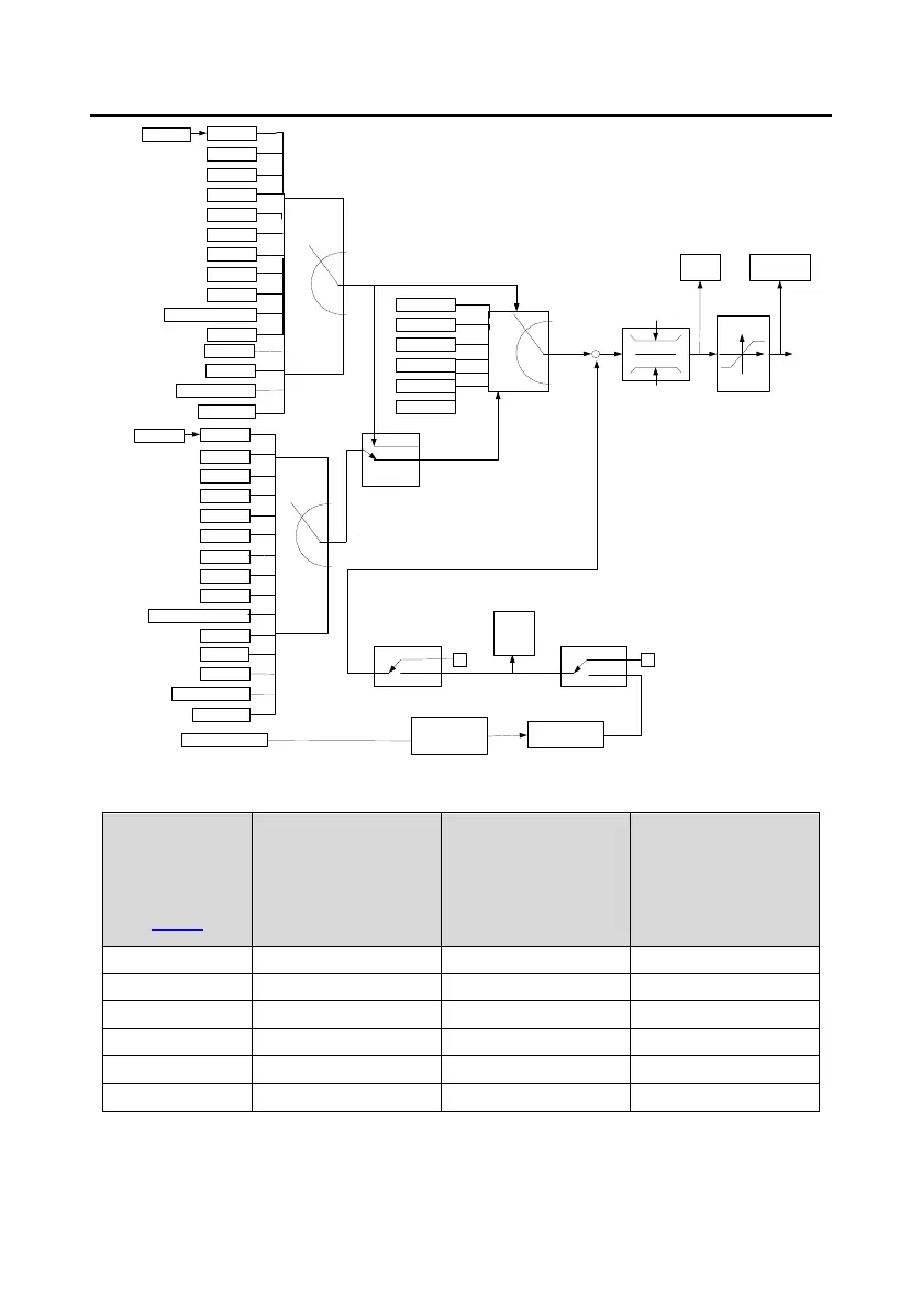
The VFD supports switchover between different reference channels, and the rules for channel
switchover are shown as follows.
Present
reference
channel
P00.09
Multifunction
terminal function 13
(Switch from
channel A to channel
Multifunction
terminal function 14
(Switch from
combined setting to
Multifunction
terminal function 15
(Switch from
combined setting to
Note: "/" indicates this multifunction terminal is invalid under present reference channel.
When setting the auxiliary frequency inside the VFD via multi-function terminal UP (10) and DOWN
 Loading...