2011-07-01/00561073 [SCR Power Controller TYA202] 35
3 Electrical Connection
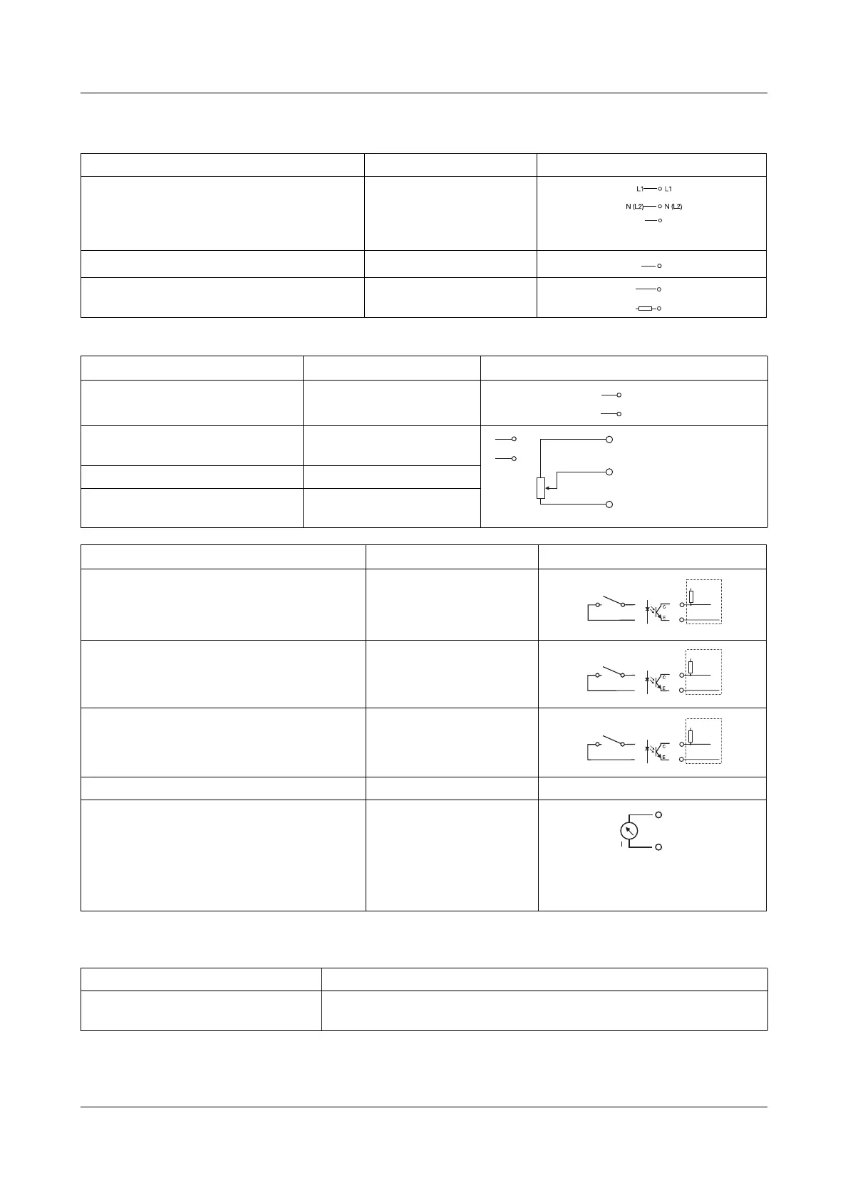
3.3 Connection diagram
Control section
Master/slave
connection
Connection for Screw terminals Connection side Device side
Voltage supply for control electronics
(corresponds to the max. load voltage of
the
ordered device type)
L1
N/L2
V
Protective earth PE
Load connection in the
power section U1
U2
Connection for screw terminal X2_1
Connection side Device side
Current set point input 1
2
Voltage set point input 3 (GND)
4
Output DC 10V fixed voltage 5
Ground potential 6 (GND)
External manual
adjustment with po-
tentiometer
Connection for Screw terminal X2_2
Connection side Device side
Firing-pulse 8
7 (GND)
Binary input 1 9
11 (GND)
Binary input 2 10
11 (GND)
GND 7, 11 Ground potential
Analog output
Different internal controller sizes can be
output as a standard signal 0(4)...20mA,
0(2)...10V, 0(1)...5V.
v Chapter 10.4 „Analog output (actual
value output, only master)“
12
Connection for RJ 45 bush X8
three-phase current economy circuit
Master-slave mode
1:1 patch cable