4 Operation
40 2011-07-01/00561073 [SCR Power Controller TYA202]
actual value, set point value load resistance, device temperature and power.
This information is also shown in the diagnosis window of the setup program.
v Chapter 7 „Setup program“
4.1.2 Display of measured values
Measured value
overview
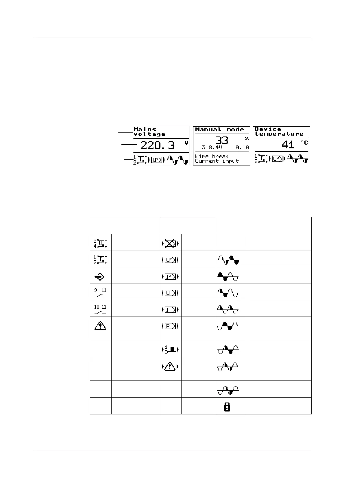
In this level, the designation of the measured value is shown in the top line and
the numerical value with the unit in the center.
The info line at the bottom shows the signal flow diagram: Input ->
Processing -> Output in the device at a glance. It is also used to display
temporary statuses (e.g. error messages).
v Chapter 8 „Fault messages and alarms“
Meaning of the
symbols in the
info line
Designation
Measured value
Info line or error
Input signal Cascade
control
Operating mode
load output
Voltage None
Current U
2
Soft start with phase
angle control
Interface I
2
Burst-firing mode
Binary input1 U Burst-firing mode with
a start
Binary input2 I Half-wave control
Input signal
incorrectly
configured
P Logic, general
Logic
(switch)
Logic with a start
Invalid
control
configured
Logic with a default
values
Logic with a start and
a default values
Firing-pulse
inhibit


 To Next Page