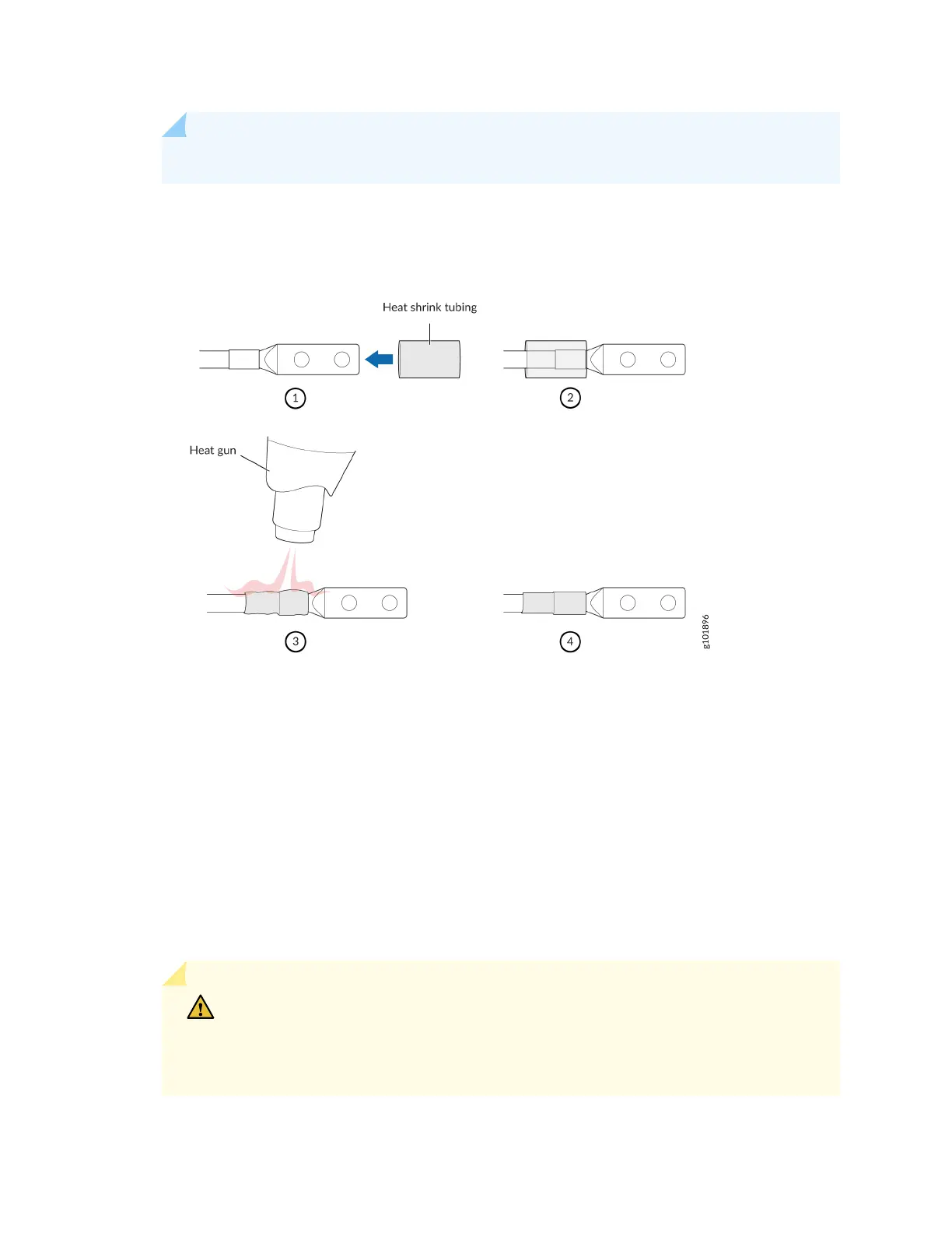
NOTE: Do not overheat the tubing.
Figure 54: How to Install Heat-Shrink Tubing
8. Remove the clear plasc cover from the terminal studs on the faceplate and remove the nut and
washer from each of the terminal studs.
9. Secure each power cable lug to the terminal studs, rst with the at washer, then wish the split
washer, and then with the nut. Apply between 23 lb-in (2.6 Nm) and 25 lb-in (2.8 Nm) of torque to
each nut. Do not overghten the nut. (Use a 7/16 in. [11 mm] torque-controlled driver or socket
wrench.) See Figure 55 on page 184.
• On INP0, aach the posive (+) DC power source cable lug to the RTN (return) terminal. Repeat
this step for INP1 if you are using two feeds.
• On INP0, aach the negave (–) DC power source cable lug to the –48 V (input) terminal.
Repeat this step for INP1 if you are using two feeds.
CAUTION: Ensure that each power cable lug seats ush against the surface of the
terminal block as you are ghtening the nuts. Ensure that each nut is properly
threaded onto the terminal stud. You must be able to spin the nuts freely with your
ngers when they are placed onto the terminal stud for the rst me. Applying
182