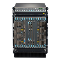
The SF modules install horizontally into the front of the chassis. If any slots are empty, you must install a
cover panel.
The SF module has the following components:
• Chassis management Ethernet switch
• I2C bus logic, used for low-level communicaon with each component
• Component redundancy circuitry
• Control Board/Roung Engine primary-role mechanism
• Gigabit Ethernet switch that is connected to the embedded CPU complex on all components
• Control eld-programmable gate array (FPGA)—Provides the Peripheral Component Interconnect
(PCI) interface to the Roung Engine
• 1000Base-T Ethernet controller—Provides a 1-Gbps Ethernet link between the Roung Engines
• Ethernet switch—Provides 1-Gbps link speeds between the Roung Engine and the line cards
• External clock interface—Allows BITS or GPS clock source input to the centralized ming circuit, or
allows centralized ming to be output to BITS or GPS
• Circuits for chassis management and control
• Power circuits for the Roung Engine and the Switch Fabric
• SF module LEDs—Indicate system status. (See
Switch Fabric Module LEDs in an EX9200 Switch
).
• Ejector levers—Used for installing and removing the SF module
• Capve screws—Secure the SF module in place
SEE ALSO
Installing an SF Module in an EX9200 Switch
Removing an SF Module from an EX9200 Switch
Taking the Host Subsystem Oine in an EX9200 Switch
70

 Loading...