Load Edge Series
Names and Functions 31
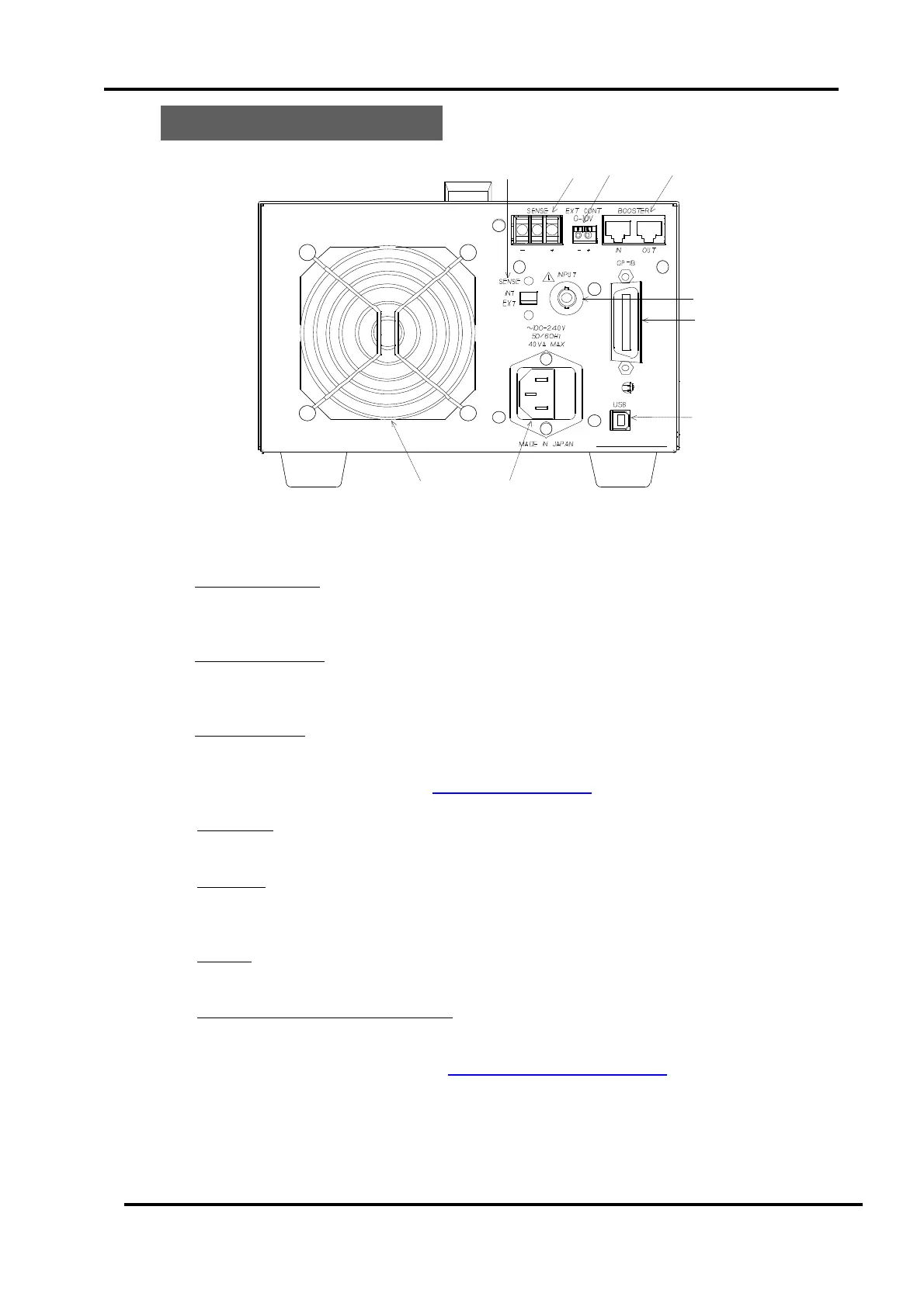
3.2 Rear Panel
Fig. 3-2-1 Rear panel.
(1) INPUT connector
When option RC-02A (Ripple Noise converter) is built- in, a BNC connector is added
there. Otherwise, the hole is occluded with a cover.
(2) GP-IB Connector
I/F conforming to IEEE488.1. You can control this product from a general GP-IB
controller.
(3) USB Connector
A USB connector conforming to USB1.1 for connecting a PC. With attached device driver
and control library, you can control from your PC.
For more detailed, refer to → “ Ch.8 Remote control ”.
(4) AC Inlet
For connecting AC power cord. The input voltage range of this product is 100V-240V.
(5) Air outlet
Air can be exhausted through this air outlet.
Note: Please do NOT block the air outlet.
(6) Booster
External control input terminals
(7) Ext. Control Input BNC Connector
For inputting external Voltage for controlling load level.
The input range is 0-10V.
For more information, refer to → “ 5.9 Ext. Control (EXT) mode”.
 Loading...