Load Edge Series
Connections 23
2.3 To achieve fast load response
To achieve fast load response as described in the specification of this product, pay attention to
the following:
1. Negative effect by inductance
Back electro motive force caused by both inductance of load cable and internal
inductance of this product would influence rising time. Needless to say, current could
not be sunk if the voltage drop caused by the back electro motive force exceeds volt
between load terminals, because there is no voltage potential difference left.
This product is designed to minimize the internal inductance but is not zero, so it is
necessary that some level of voltage potential difference need to be presented
between the load terminals. For example, 5V needs to be presented between the load
terminals to set and realize 25A/usec slew rate. Because voltage drop is caused by
the inductance of load cables, it is suggested that the inductance caused by load
cables should be minimize as much as possible. Voltage difference between inputs
terminals is necessary even internal inductance is very low. Use lowest possible
cable to minimize cable inductance.
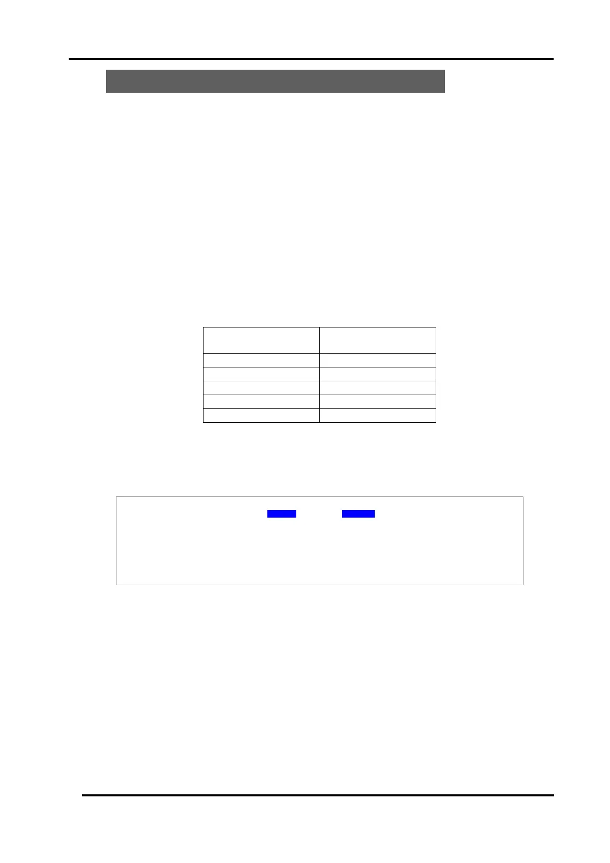
Voltage between load
terminals Vin(V)
Table 2-3-1 Maximum slew rate settable in accordance with the voltage presented at between
load terminals.
・ With optional low inductance cable LL-050, the inductance can be reduced by
typically 80% comparing with normal cable (equivalent to 7AWG). The
inductance value of the LL-050 is 80nH(Typ)
 Loading...