To connect the Model 2016 THD Multimeter to the IEEE-488 bus, follow these steps:
1. Line up the cable connector with the connector located on the rear panel. The connector
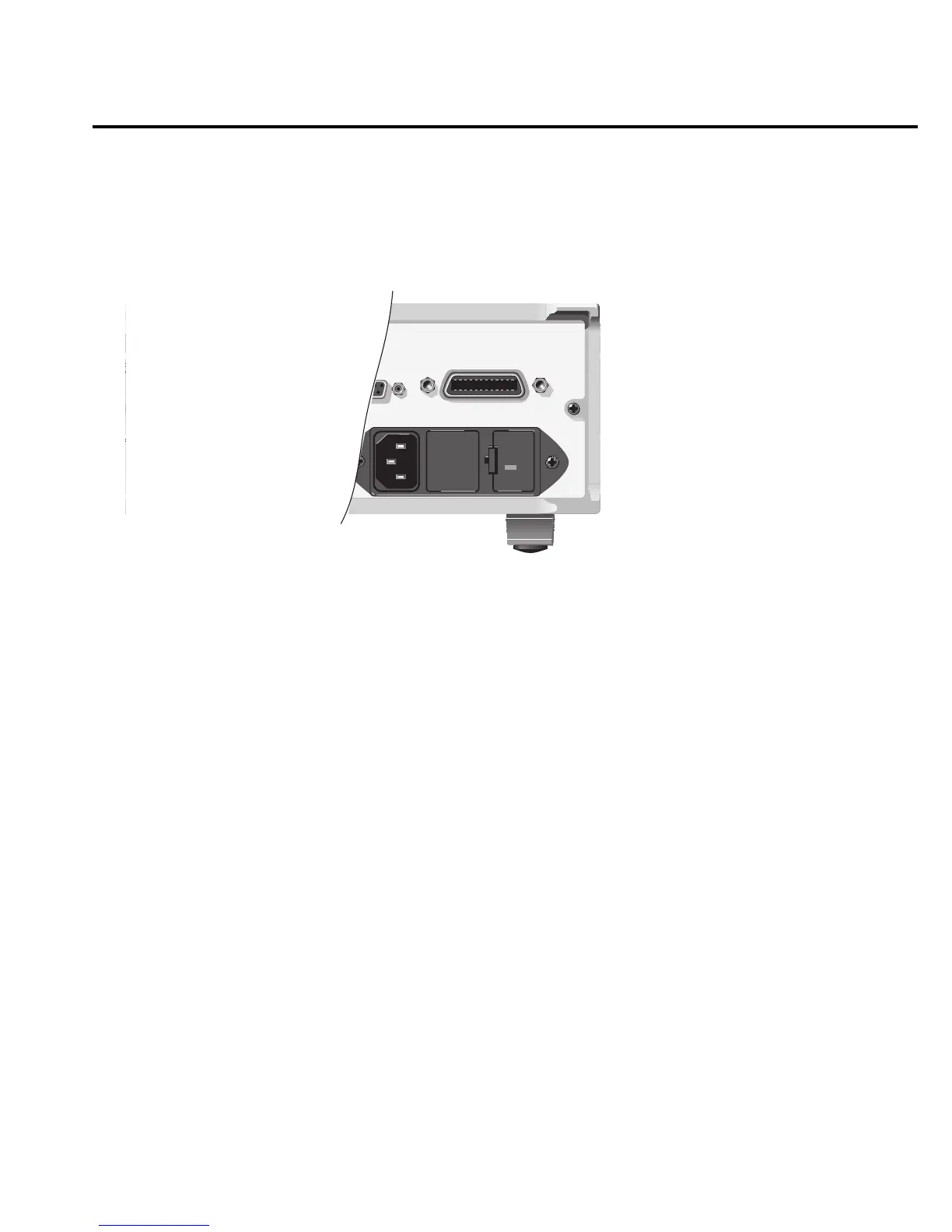
is designed so that it will fit only one way. Figure 4-4 shows the location of the IEEE-488
connector.
2. Tighten the screws securely, making sure not to over tighten them.
3. Connect any additional connectors from other instruments as required for your
application.
4. Make certain that the other end of the cable is properly connected to the controller. Most
controllers are equipped with an IEEE-488 style connector, but a few may require a
different type of connecting cable. See your controllers instruction manual for
information about properly connecting to the IEEE-488 bus.
NOTE You can only have 15 devices connected to a IEEE-488 bus, including the controller.
The maximum cable length is either 20-meters or 2-meters times the number of
devices; whichever is less. Not observing these limits may cause erratic bus
operation.
1
3 5
2
4 6
VMC
EXT TRIG
FUSE LINE
100 VAC
120 VAC
250 mAT
(SB)
220 VAC
240 VAC
500 mAT
(SB)
WARNING:NO INTERNAL OPERATOR SERVICABLE PARTS,SERVICE BY QUALIFIED PERSONNEL ONLY.
WARNING:NO INTERNAL OPERATOR SERVICABLE PARTS,SERVICE BY QUALIFIED PERSONNEL ONLY.
CAUTION:FOR CONTINUED PROTECTION AGAINST FIRE HAZARD,REPLACE FUSE WITH SAME TYPE AND RATING.
CAUTION:FOR CONTINUED PROTECTION AGAINST FIRE HAZARD,REPLACE FUSE WITH SAME TYPE AND RATING.
RS232
120
MADE IN
U.S.A.
INPUT
500V
PEAK
V
K
1000V
PEAK
TRIGGER
LINK
SENSE
Ω 4W
HI
LO
!
LINE RATING
50, 60
25 VA MAX
IEEE-488
(CHANGE IEEE ADDRESS
FROM FRONT PANEL)
!
!
42V PEAK
RCE
PUT
SOURCE
OUTPUT
INV/PULSE
!
igure 4-4
EEE-488 connector
location
Remote Operation 4-9