2. Select the measurement function by pressing SHIFT then THD.
3. Pressing AUTO toggles autoranging. Notice the AUTO annunciator is displayed with
autoranging. If you want manual ranging, use the RANGE ▲ and ▼ keys to select a
measurement range consistent with the expected voltage.
NOTE Pressing AUTO to turn off autoranging for distortion readings displays a message
indicating the present range.
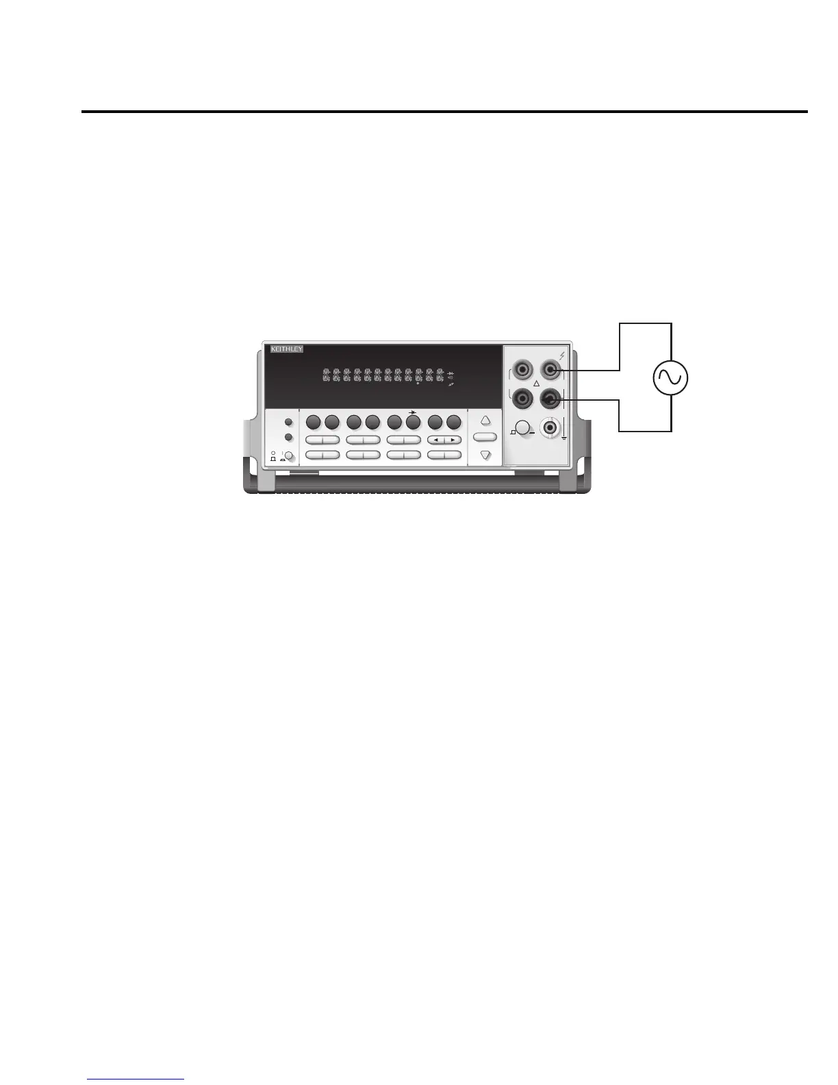
4. Connect test leads to the source as shown in Figure 2-11.
CAUTION Do not apply more than 1000V peak to the input or instrument damage
may occur. The voltage limit is subject to the 8×10
7
V•Hz product.
5. Observe the display. If the “UDRFLW %THD” or “UDRFLW dB” message is displayed
(2% of range), select a lower range until a normal reading is displayed (or press AUTO
for autoranging). Use the lowest possible range for the best resolution.
NOTE Pressing the AUTO key to turn off autorange for distortion readings will display a
short message indicating the present range.
When the fundamental frequency is outside the 20Hz to 20kHz range, an underflow or
overflow condition exists. When a traping filter is enabled, the range can be much
narrower, depending on the type of filter enabled.
6. Take readings from the display.
NOTE When measuring distortion on the 100mV range or autoranging, open input leads
cause the distortion modes to display apparently valid readings. This is noise pickup
at the power line frequency. The amplitude of the signal depends on the type and
length of input connections. If the issue cannot be resolved by selecting a higher
range, place a resistor across the input leads creating an underflow condition when
the leads are open. The resistor value depends on the amount of noise present, but
typically is 50kΩ to 150kΩ.
Input Impedance = 1M and <100pF
Caution: Maximum Input = 1000V peak, 8 × 10
7
V•Hz
2016 THD MULTIMETER
RANGE
!
F
500V
PEAK
FRONT/REAR
3A 250V
AMPS
HI
INPUT
LO
SENSE
Ω 4 WIRE
INPUTS
350V
PEAK
1000V
PEAK
AUTO
SHIFT
LOCAL
POWER
RANGE
R
SHIFT
CH1REM
TALK
LSTN
SRQ
STAT
REL FILT
4W
BUFFER
MATH
REAR
SCAN
TIMER
STEP CH2 CH3 CH4 CH5 CH6 CH7 CH8 CH9 CH10
HOLD TRIG FAST MED SLOW AUTO ERR
EXIT ENTER
DIGITS RATE
RELFILTER
TRIG
EX TRIG
STORE
RECALL
SOURCE
MEAS
DCV
DCI
MATH
THD
dBm
ACV
ACI
Ω2 Ω4
FREQ
TEMP
dB
CONT
PERIOD TCOUPL
LIMITS ON/OFFDELAY
HOLD
SAVE SETUP
CONFIG HALT
TEST
RS232
GPIB
CAL
STEP SCAN
THD
AC Voltage
Source
Model 2016
gure
-
istortion
measurements
Basic Measurements 2-41