Connections
Assuming factory default conditions, the basic procedure is as follows:
1. Connect test leads to the INPUT HI and LO terminals of the Model 2016. Either the front
or rear inputs can be used; place the INPUTS button in the appropriate position.
2. Select the FREQ or PERIOD function.
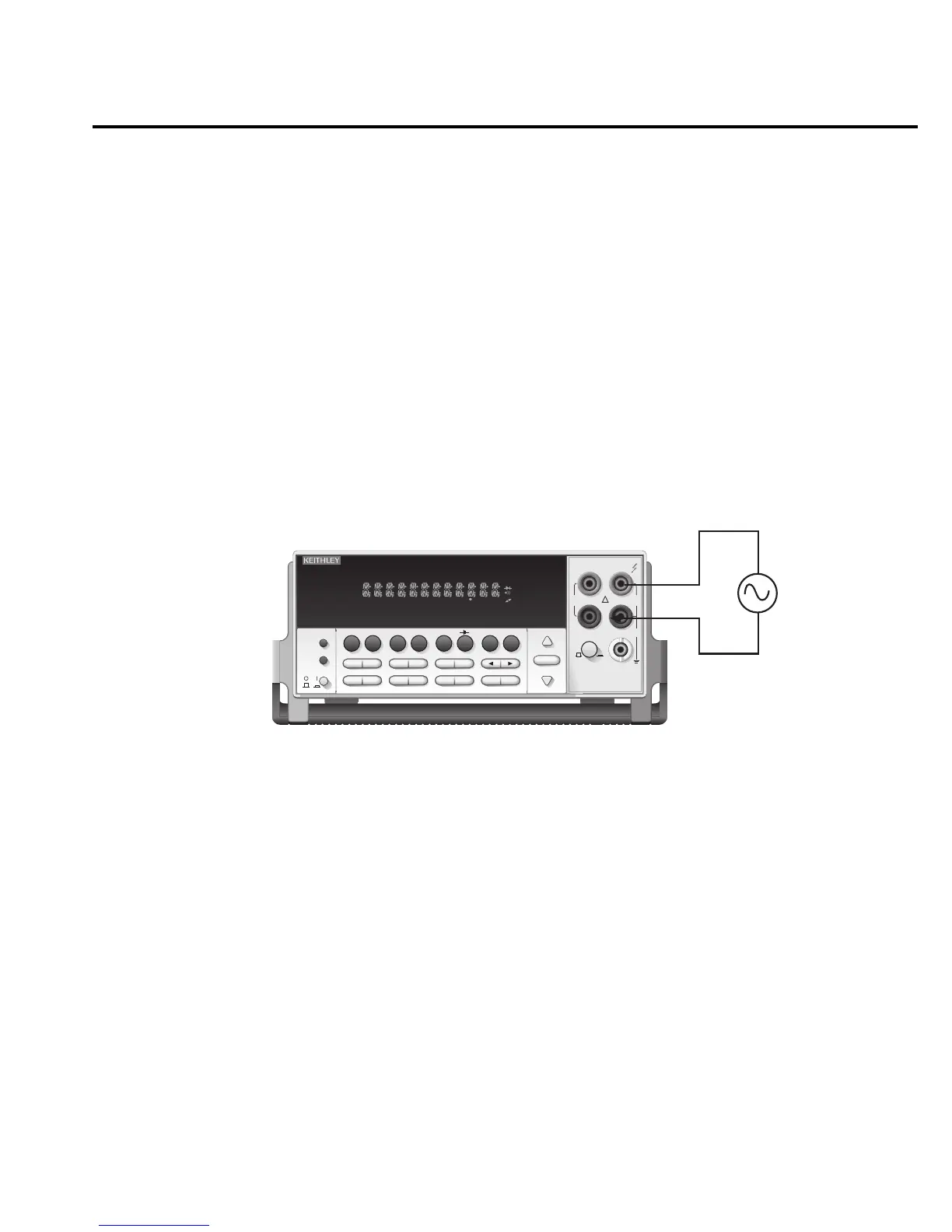
3. Connect test leads to the source as shown in Figure 2-7.
CAUTION Do not exceed 1000V peak between INPUT HI and INPUT LO or
instrument damage may occur.
4. Take a reading from the display.
See Section 3 — Measurement Options for information that explains the configuration
options for frequency and period measurements.
Input Impedance = 1M in parallel with <100pF
Caution: Maximum Input = 1000V peak, 8
× 10
7
V•Hz
2016 THD MULTIMETER
RANGE
!
F
500V
PEAK
FRONT/REAR
3A 250V
AMPS
HI
INPUT
LO
SENSE
Ω 4 WIRE
INPUTS
350V
PEAK
1000V
PEAK
AUTO
SHIFT
LOCAL
POWER
RANGE
R
SHIFT
CH1REM
TALK
LSTN
SRQ
STAT
REL FILT
4W
BUFFER
MATH
REAR
SCAN
TIMER
STEP CH2 CH3 CH4 CH5 CH6 CH7 CH8 CH9 CH10
HOLD TRIG FAST MED SLOW AUTO ERR
EXIT ENTER
DIGITS RATE
RELFILTER
TRIG
EX TRIG
STORE
RECALL
SOURCE
MEAS
DCV
DCI
MATH
THD
dBm
ACV
ACI
Ω2 Ω4
FREQ
TEMP
dB
CONT
PERIOD TCOUPL
LIMITS ON/OFFDELAY
HOLD
SAVE SETUP
CONFIG HALT
TEST
RS232
GPIB
CAL
STEP SCAN
THD
AC Voltage
Source
Model 2016
Figure 2-7
Frequency
and period
measurements
Basic Measurements 2-25