Keysight 16860 Series Portable Logic Analyzer Service Guide 123
Removing, Replacing, or Returning 16860 Series Logic Analyzer Assemblies 6
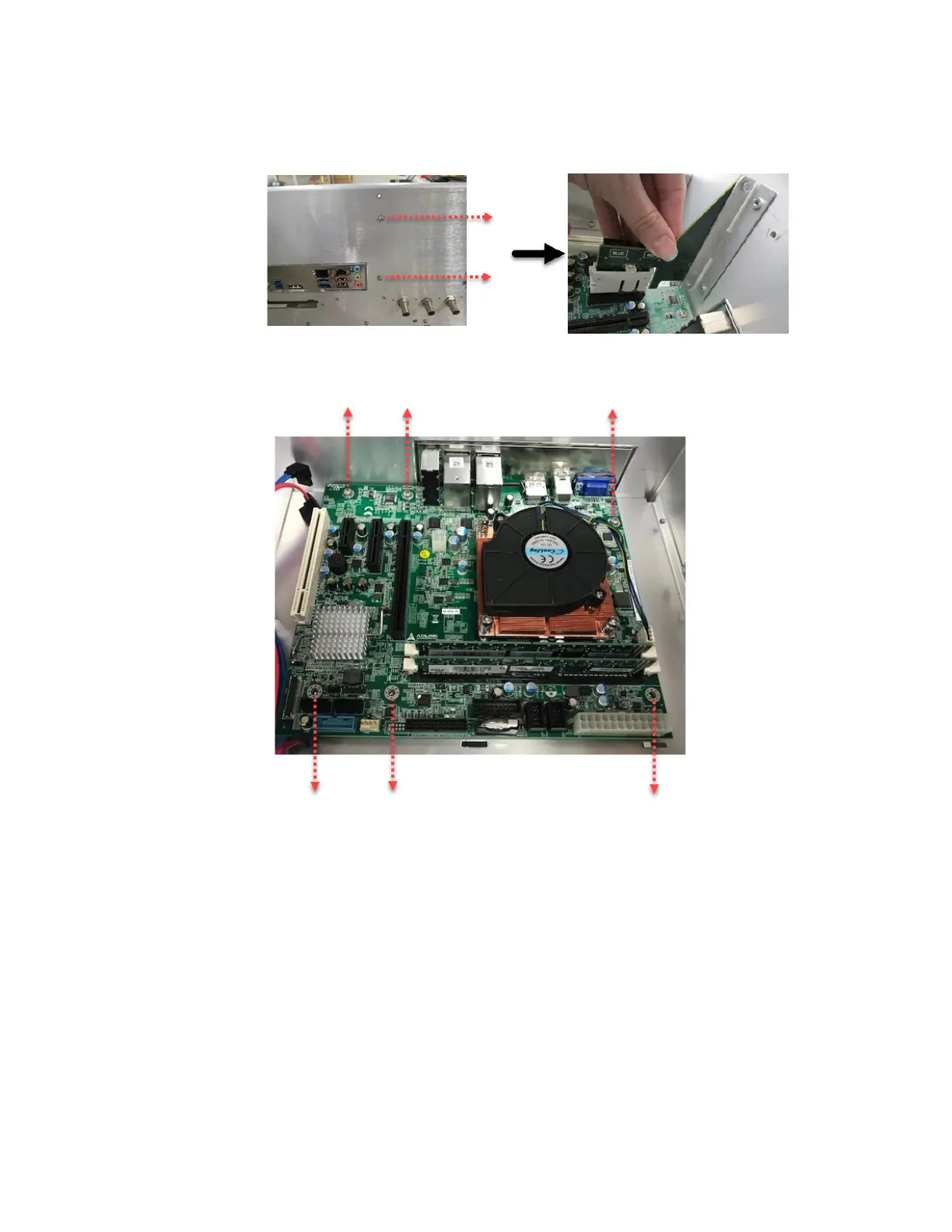
3 Using a Torx T15 screwdriver, remove the six screws that secure the motherboard. These are
indicated in the photo below.
4 Remove the motherboard.
5 Reverse this procedure to install the motherboard.