Keysight 16860 Series Portable Logic Analyzer Service Guide 63
Testing 16860 Performance 3
Determine Maximum Data Rate for Single Clock Mode
The single clock test measures the maximum data rate for the single clock mode. This test measures
data rates for Rising, Falling, and Both Edge modes. Using Both Edge clocking, it verifies data rates
on all pods. The measurement is done in two parts:
• The first part is to determine the maximum clock rate that the analyzer will run at.
• The second part is to verify that the data captured by the analyzer is correct; markers are used to
verify the data patterns.
Single Clock Rising Edge - Maximum Clock Rate
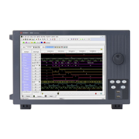
1Load the SingleClock_NoMarker.ala configuration file. If asked to save the current configuration file,
click No.
2 Verify that the Generator is set to 714 MHz as a starting point.
3 Disconnect the U4203A Flying Lead Probe Set from channels 1 & 2 of the 81134A pulse
generator output (Bits 2, 6, 10, 14) and clock leads.
4 Connect the probe set from Pod 1 of logic analyzer to the pulse generator channels 1 & 2 output.
• Clock to Channel 1 Output
• Clock (NOT) Channel 1 Output (not)
• Bits 2 & 10 to Channel 2 Output
• Bits 6 & 14 to Channel 2 Output (not)
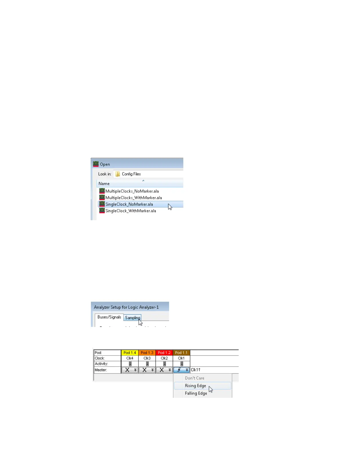
5 Open the Sampling tab in the Analyzer Setup dialog by clicking the Sampling Setup Icon.
6 In the clock assignment area, set Pod 1 Clock to Rising Edge.
7 Close the dialog windows by clicking OK.