3 Testing 16860 Performance
30 Keysight 16860 Series Portable Logic Analyzer Service Guide
Set Up the Test Equipment
This section explains how to set up the test equipment for the maximum state data rate test.
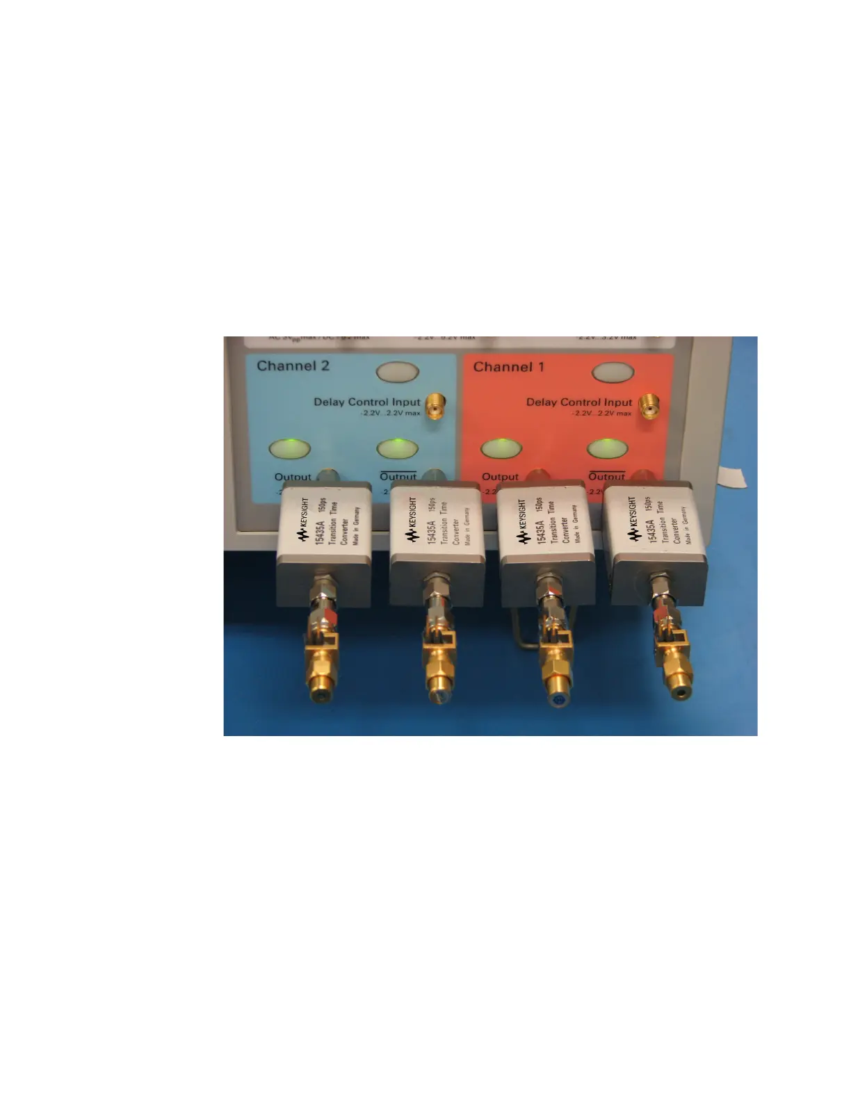
1 Connect Transition Time Converters (if required) to each of the four outputs of the pulse
generator: Channel 1 OUTPUT, Channel 1 OUTPUT (not), Channel 2 OUTPUT, Channel 2 OUTPUT
(not).
2 Connect the four SMA/Flying Lead test connectors (see “Assemble the SMA/Flying Lead Test
Connectors" on page 27) with 50 ohm terminators to the Transition Time Converters on the 4
pulse generator outputs. (If Transition Time Converters are not required, connect the SMA/Flying
Lead test connectors directly to the pulse generator outputs.)
3 Turn on the Pulse Generator. Let all of the test equipment and the logic analyzer warm up for 30
minutes before beginning any test.
4 Load the default configuration into the 81134A Pulse Generator.
•Select Main
•Hit Recall
• Press 0
5 Setup the pulse generator according to the following.
a Set the frequency of the pulse generator:
In this test procedure, the logic analyzer uses both edges of the clock to acquire data. The test
frequency is half the test clock rate because data is acquired on both the rising edge and the
falling edge of the clock. For the multiple clocks mode, set the frequency to:
• Base Option: Temporarily License the analyzer to full speed and test at 700 Mb/s plus 2%
(714 Mb/s). Set the generator to half this or 357 MHz.