Keysight 16860 Series Portable Logic Analyzer Service Guide 27
Testing 16860 Performance 3
Assemble the SMA/Flying Lead Test Connectors
The SMA/Flying Lead test connectors provide a high-bandwidth connection between the logic
analyzer and the test equipment. The following procedure explains how to fabricate the four required
test connectors.
Table 3 Materials Required for SMA/Flying Lead Test Connectors
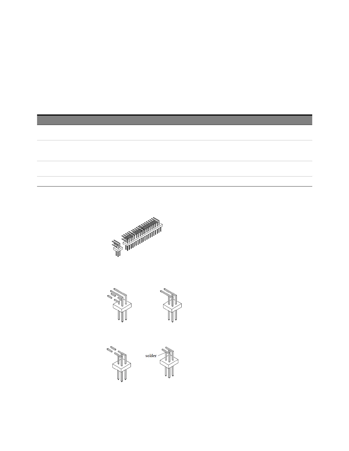
1 Prepare the pin strip header:
a Cut or cleanly break a 2 x 2 section from the pin strip.
b Trim about 1.5 mm from the pin strip inner leads and straighten them so that they touch the
outer leads.
c Trim about 2.5 mm from the outer leads.
d Using a very small amount of solder, tack each inner lead to each outer lead at the point where
they are touching.
Material Critical Specification Recommended Model/Part
SMA Board Mount Connector (Qty 8) Cinch 142-0701-801
(see www.cinch.com )
Pin Strip Header (Qty 1, which will be separated) 0.100" X 0.100" Pin Strip Header, right angle, pin
length 0.230", two rows, 0.110" solder tails, 2 X 40
contacts
3M 2380-5121TG or similar 2- row with 0.1" pin
spacing
SMA 50 ohm terminators (Qty 4) Minimum bandwidth 2 GHz Cinch 142-0801-866 50 ohm Dummy Load Plug or
similar
SMA m-m adapter (Qty 4) Cinch 142-0901-811 SMA Plug to Plug or similar