3 Testing 16860 Performance
72 Keysight 16860 Series Portable Logic Analyzer Service Guide
15 Click the Stop toolbar button to stop the data acquisition.
16 Note the generator frequency setting. This will be used in the next section to verify the data rate.
Single Clock Both Edges - Pod 1 Data - Setup for Maximum Data Rate
1 On the 81134A, select the channel 2 setup screen. This is the data channel.
2 Set the Channel 2 Freq. Divider to 1.
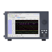
3Load the SingleClock_WithMarker.ala configuration file. If asked to save the current configuration
file, click No.
4 Verify that the Generator is set to the frequency found in the last section as a starting point.
5 Open the Sampling tab in the Analyzer Setup dialog by clicking the Sampling Setup Icon.
6 Adjust the sample position using the procedure described earlier by clicking the Eye Scan: Sample
Position and Thresholds button. Select the eye closest to -1 ns.
7 Close the dialog windows by clicking OK.
Single Clock Both Edges - Pod 1 Data - Measuring Maximum Data Rate
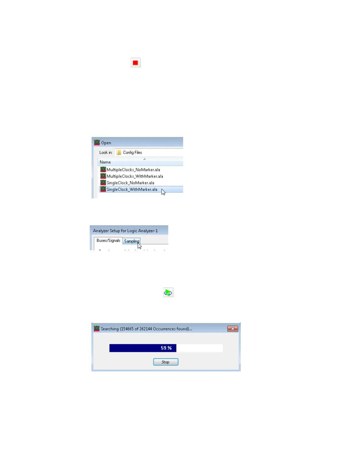
1 Select the Run Repetitive icon . Let the logic analyzer run for about 1 minute. The analyzer will
acquire data and the Listing Window will continuously update. A marker search window will
appear and show progress.
2 If incorrect data is found, the following window will appear. The data in the listing window should
be A's & 5's.