Keysight 16860 Series Portable Logic Analyzer Service Guide 73
Testing 16860 Performance 3
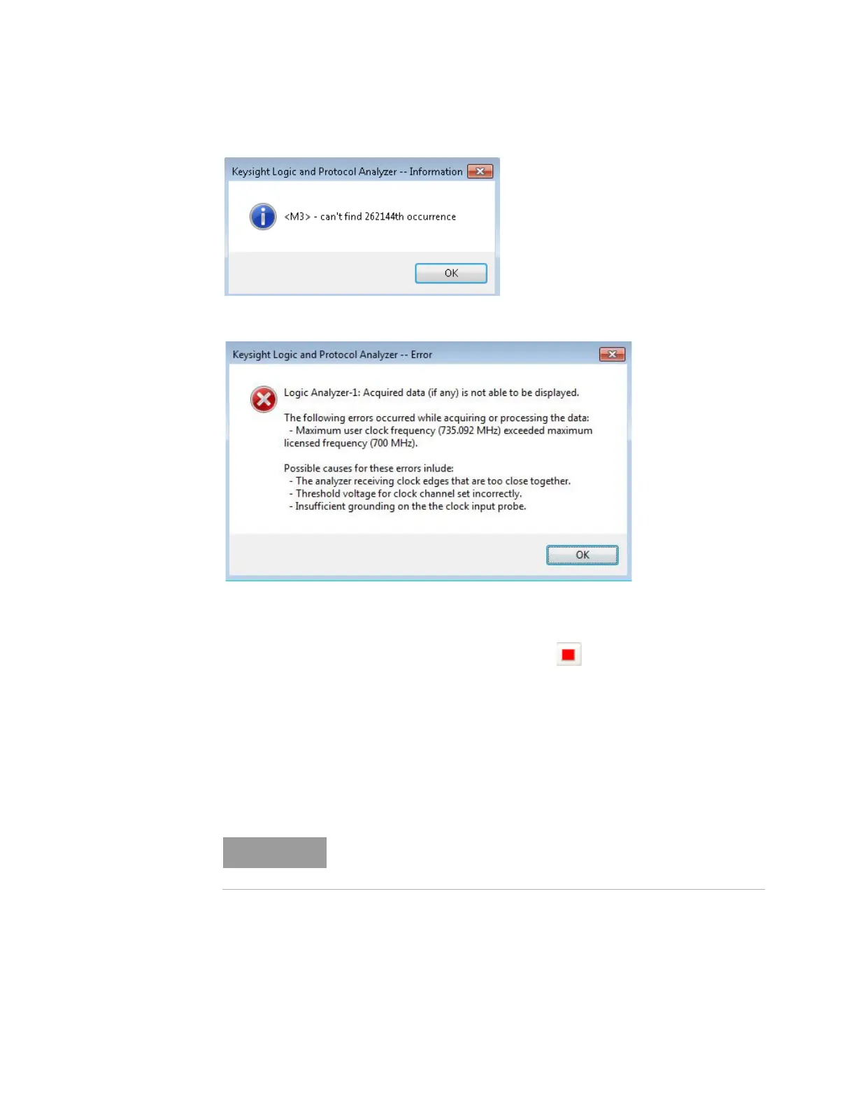
3 If the clock rate is too high, this error message may occur.
4 If either of these messages occur, the generator frequency should be lowered, Eye Scan should
be rerun and the test should be rerun.
5 Lower the generator frequency by 1 MHz and rerun the test.
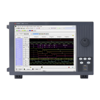
6 After the analyzer runs for about 1 minute, select the Stop button to stop the acquisition. If
the "can't find occurrence" window does not appear, then the analyzer has found good data.
7 For Single Clock for Both Edges Pod1, record the generator frequency and the Data Rate in the
"Maximum State Data Rate" section of the “Performance Test Record. Note: For Both Edges
Clocking, the data rate is twice the generator frequency.
Single Clock Both Edges - Pod 2 Data - Setup for Maximum Data Rate
The next set of tests use the Pod 1 clocks to verify the data rate on the other pods in Single Clock
mode.
1 Verify that the Generator is set to the frequency found in “Single Clock Both Edges - Maximum
Clock Rate section above.
2 Disconnect the U4203A Flying Lead Probe Set from channels 2 of the 81134A pulse generator
output (Bits 2, 6, 10, 14). Do not disconnect the clock leads from Pod 1.
3 Connect the probe set from Pod 2 of logic analyzer to the pulse generator channels 2 outputs.
The starting frequency for the following tests (Pods 2-8) will be the frequency
found in the "“Single Clock Both Edges - Maximum Clock Rate" section
above.