Chapter 1: Installation and wiring
P/N 3102352-EN • REV 005 • ISS 28DEC18 31
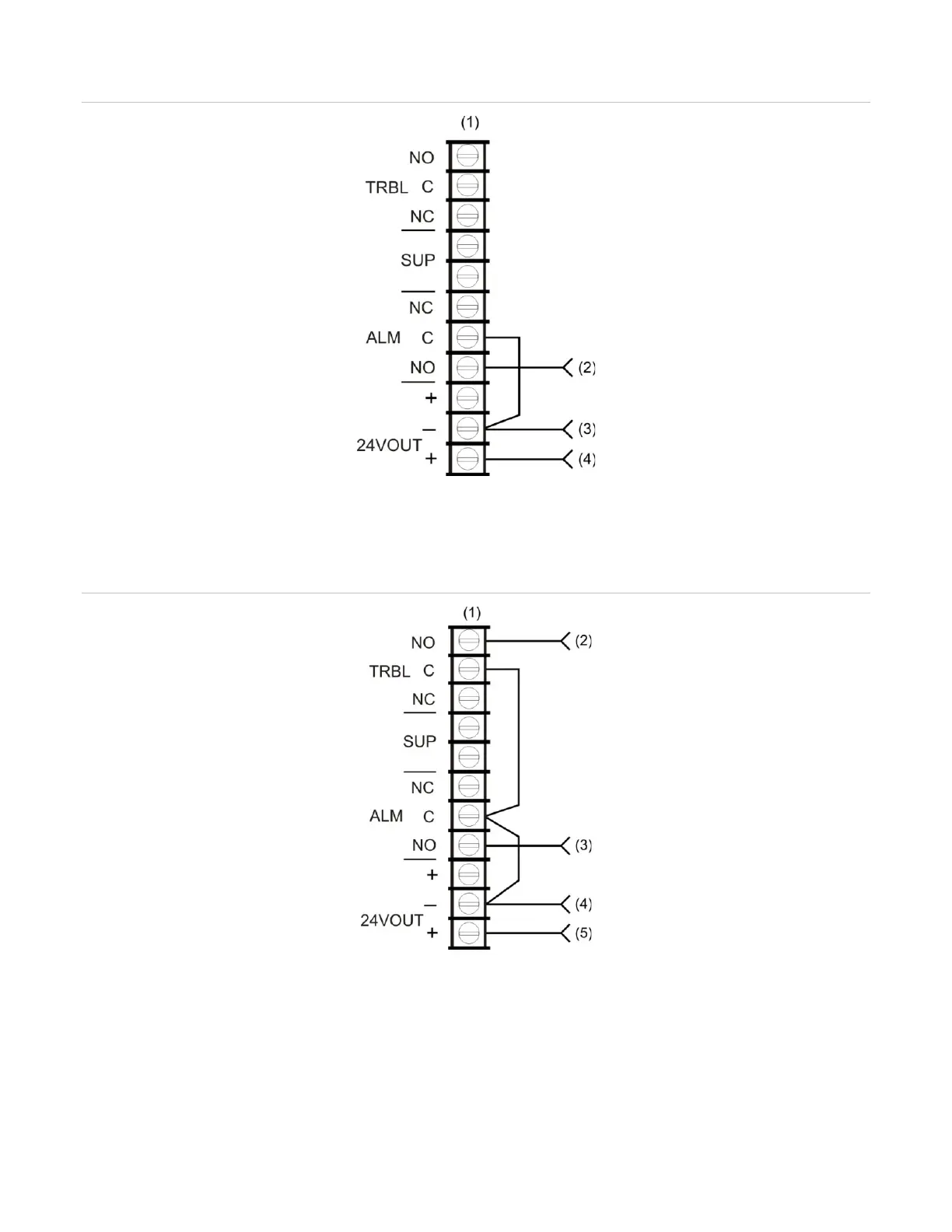
Figure 41: Alarm transmitted only
(1) Control panel TB3
(2) From ALRM on RPM (brown wire)
(3) From COM on RPM (black wire)
(4) From +24 on RPM (red wire)
Figure 42: Alarm and trouble transmitted on a single circuit
2) From TRBL on RPM (yellow wire)
(3) From ALRM on RPM (brown wire)
(4) From COM on RPM (black wire)
(5) From +24 on RPM (red wire)
Note: JP1 on the RPM must be OUT.