EN UG-020 Link 6 user guide r1.0 33
The general-purpose I/Os are powered by 24 V IN or 0 V IN terminals. The terminals can receive
their power from 24 V OUT or 0 V OUT terminals, or from an external power supply. The general-
purpose I/Os contains eight (8) digital inputs, eight (8) digital outputs, four (4) analog I/Os, and
provisions for high-speed encoder inputs.
The industrial I/O panel is designed to comply with specific standards.
• Immunity requirements for safety I/O are designed for accordance with IEC 61000-6-7.
• Safety digital inputs and general-purpose digital inputs are designed for accordance with IEC
61131-2 Type 1 and Type 3.
• Safety digital outputs and general-purpose digital outputs are designed for accordance with
IEC 61131-2 Type 1 and Type 3.
• electrostatic discharge (ESD), surge, and Electrical Fast Transient(EFT) are designed for
accordance with IEC 62326-3-1.
Positive logic, which is current sinking input and current sourcing output, is supported on the
panel. Negative logic (NPN) is not supported on the panel.
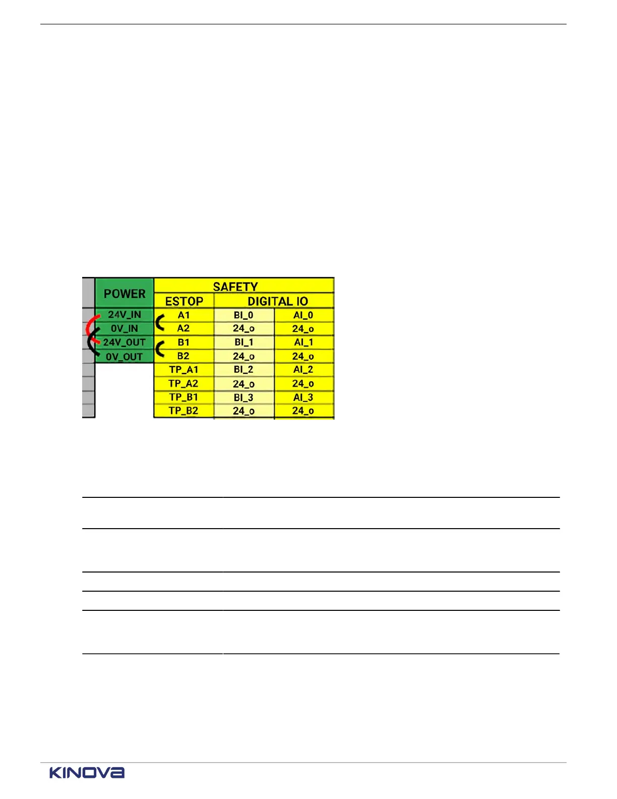
Figure 29: Default factory setting with internal supply used and external E-stop bypassed
Table 15: Industrial I/O terminals
Mechanical Min Typical Max Unit
Conductor size (UL/cUL)
16 24 American Wire
Gauge (AWG)
Conductor size (International
Electrotechnical Commission
(IEC))
0.2 1.5
mm
2
Stripping Length 8 10 mm
Terminal pitch 3.5 mm
Ferrule Deutsches Institut
für Normung (DIN)
46228-4
Related topics
Installing the external 3-position enabling device on page 259
+1 514-277-3777 kinovarobotics.com
© 2022 Kinova inc. All rights reserved.