EN UG-020 Link 6 user guide r1.0 78
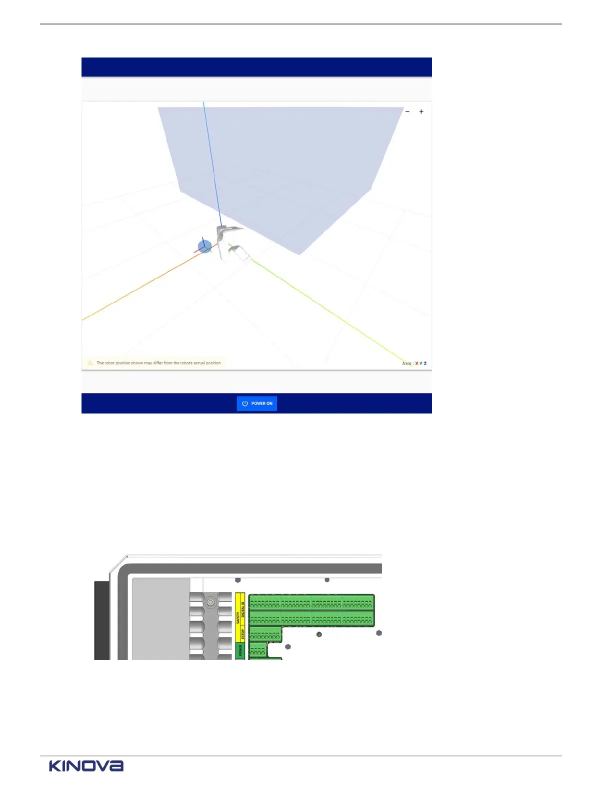
Figure 60: Visualization pane with tool sphere, robot, and other protection zones
Zoom in, zoom out, and view the zones from different angles.
Safety I/O
Each input safety function can be assigned through KortexWebApp to one of eight channels.
Each output safety function can be assigned to one or more of the eight channels.
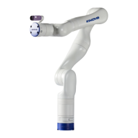
Figure 61: Location of connectors for the Safety I/O equipment
When the physical equipment is connected to the controller through the green slots, it can then be
assigned a specific behavior on the corresponding channel in KortexWebApp. The channels are
numbered 0 through 7.
+1 514-277-3777 kinovarobotics.com
© 2022 Kinova inc. All rights reserved.