EN UG-020 Link 6 user guide r1.0 40
Emergency stop inputs
Emergency stop devices must comply with ISO 13850:2015.
Link6 requires an emergency stop device with two (2) Normally Closed (NC) redundant contacts.
The terminal connections belong to the SAFETY - ESTOP terminal group.
Table 29: Emergency stop terminal connections
Label Purpose
AI 24 V wetting port
A2 Channel A - digital input
B1 24 V output
B2 Channel B - digital input
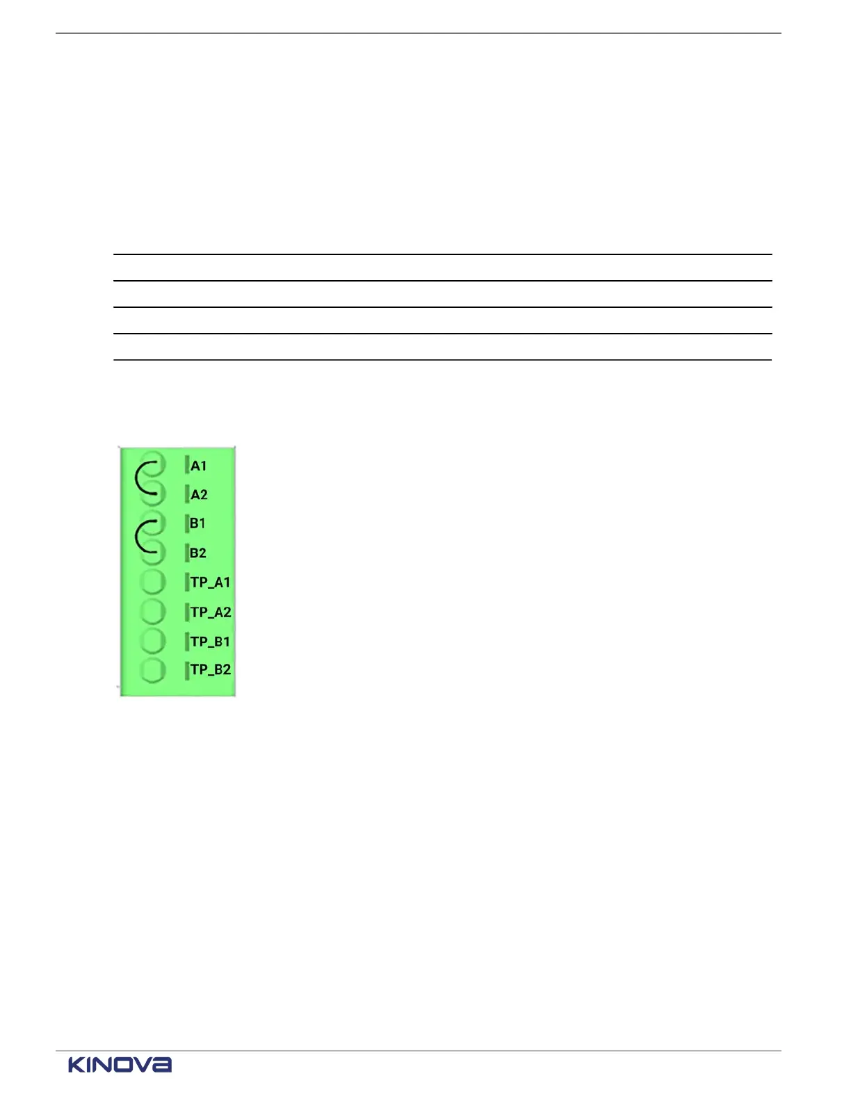
A typical installation involves a teach pendant that is connected on the front panel. The
emergency stop is an integrated part of the teach pendant. The only thing to do is to install a
jumper wire on A1, A2, B1, and B2.
Figure 36: Terminal connections with jumper on A1, A2, B1, and B2 when the teach pendant is
connected
+1 514-277-3777 kinovarobotics.com
© 2022 Kinova inc. All rights reserved.
 Loading...